Ceramic fiber toughened CVD silicon carbide (SiC) composite and preparation method and application thereof

A composite material and ceramic fiber technology, applied in the field of ceramic matrix composite material preparation, can solve problems such as CVDSiC coating peeling off, achieve the effect of improving interface bonding force and solving the problem of coating cracking

Active Publication Date: 2019-10-25
CENT SOUTH UNIV
View PDF10 Cites 7 Cited by
  • Summary
  • Abstract
  • Description
  • Claims
  • Application Information

AI Technical Summary

Problems solved by technology

[0009] The present invention aims at the shortcomings of C / SiC composite materials for preparing reflectors, and provides a ceramic fiber toughened CVD silicon carbide coating and its preparation method and application, which can effectively solve the thermal problems between the existing C / SiC composite material matrix and CVD SiC coating. Matching issues, and CVD SiC coating peeling off during polishing, and the ability to toughen the coating

Method used

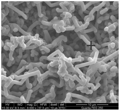
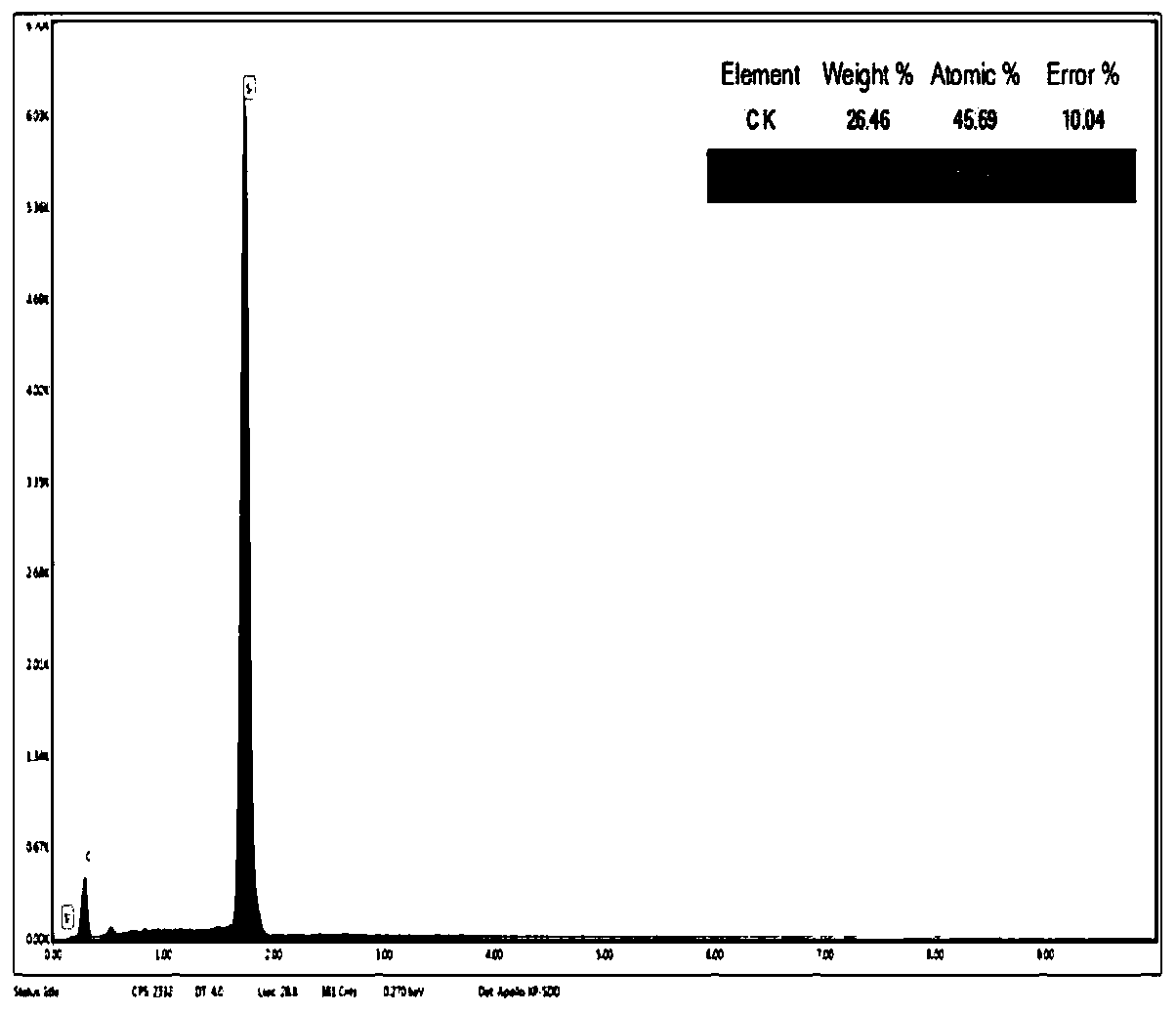
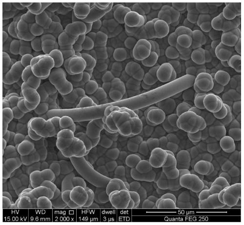

Image

  • Ceramic fiber toughened CVD silicon carbide (SiC) composite and preparation method and application thereof
  • Ceramic fiber toughened CVD silicon carbide (SiC) composite and preparation method and application thereof
  • Ceramic fiber toughened CVD silicon carbide (SiC) composite and preparation method and application thereof

Examples


Embodiment 1

[0070] Step 1: Degumming and depositing pyrolytic carbon

[0071] Under the atmosphere of propylene and nitrogen, the density of the adhesive treatment will be 0.65g / cm 3 The carbon fiber preform is deposited with pyrolytic carbon, so that the volume density of carbon fiber can reach 1.3g / cm 3 .

[0072] The degumming process described in step 1 is:

[0073] Under a protective atmosphere, the preform was treated at 800°C for 0.5 hours.

[0074] The deposited pyrolytic carbon described in step one is:

[0075] Under the atmosphere of propylene and nitrogen, propylene was used as the carbon source, nitrogen was used as the protective gas, the deposition pressure was 500pa, the deposition temperature was 950°C, the flow ratio of propylene and nitrogen was 1:1, and the deposition lasted for 200 hours.

[0076] Step two molten silicon impregnation

[0077] The preform deposited with pyrolytic carbon in step 1 is impregnated with molten silicon, embedded in silicon powder (part...

Embodiment 2

[0089] Step 1: Degumming and depositing pyrolytic carbon

[0090] Under the atmosphere of propylene and nitrogen, the density of the adhesive treatment will be 0.65g / cm 3 The carbon fiber preform is deposited with pyrolytic carbon, so that the volume density of carbon fiber can reach 1.3g / cm 3 .

[0091] The degumming process described in step 1 is:

[0092] Under a protective atmosphere, the preform was treated at 800°C for 0.5 hours.

[0093] The deposited pyrolytic carbon described in step one is:

[0094] Under the atmosphere of propylene and nitrogen, propylene was used as the carbon source, nitrogen was used as the protective gas, the deposition pressure was 500pa, the deposition temperature was 950°C, the flow ratio of propylene and nitrogen was 1:1, and the deposition lasted for 200 hours.

[0095] Step two molten silicon impregnation

[0096] The preform deposited with pyrolytic carbon in step 1 is impregnated with molten silicon, embedded in silicon powder (part...


PUM

PropertyMeasurementUnit
densityaaaaaaaaaa
densityaaaaaaaaaa
densityaaaaaaaaaa

Abstract

The invention relates to a ceramic fiber toughened CVD silicon carbide (SiC) composite and a preparation method and application thereof. The ceramic fiber toughened CVD SiC composite adopts a C/SiC composite as a substrate, SiC fibers are generated on the substrate in situ, SiC is deposited on the peripheries of the SiC fibers generated in situ, and a SiC layer toughened by the SiC fibers is formed; the SiC layer toughened by the SiC fibers is further internally provided with metal M and/or a carbide of the metal M and/or a silicide of the metal M; and M is selected from one or more of iron, cobalt and nickel. The preparation method of the ceramic fiber toughened CVD SiC composite comprises the steps: pyrolytic carbon is deposited on a carbon fiber perform firstly; then silicon melting andsiliconizing are conducted; then a catalyst, namely the metal M is introduced in a plated mode; SiC whiskers are prepared through vapor deposition; and finally, the SiC layer is prepared. The designed and prepared composite is particularly suitable for a reflector of a space camera.

Description

technical field [0001] The invention relates to a ceramic fiber toughened CVD silicon carbide composite material and a preparation method and application thereof, belonging to the technical field of preparation of ceramic matrix composite materials. Background technique [0002] As the "eyes" of space vehicles, space cameras are of great significance in the field of aerospace, and countries all over the world have also launched fierce competition in this field. Moreover, with the development of space application technology, higher and higher requirements are put forward for the launch load and the resolution of space cameras. As a key component in the space optical system, the reflector must meet the following characteristics: [0003] 1. Stable thermodynamic performance (high ratio of thermal stiffness to mass, low coefficient of thermal expansion, high thermal conductivity, low specific heat) [0004] 2. Excellent optical performance (required to be polished to the requi...

Claims


Application Information

Patent Timeline
Patent Type & Authority Applications(China)
IPC IPC(8): C04B35/80C04B35/573C04B41/90G02B5/08
CPCC04B35/806C04B35/573C04B41/009C04B41/52C04B41/90C04B2235/5248C04B2235/96G02B5/08C04B41/5144C04B41/4564C04B41/5059C04B41/4531
Inventor 李杨刘泽彦肖鹏李专陈鹏举
Owner CENT SOUTH UNIV
Why Eureka
Try Eureka