
Equipment for chamfering of sprocket part of sprocket wheel

A technology of sprocket teeth and chamfering, which is applied to gear teeth, mechanical equipment, components with teeth, etc., can solve problems such as difficult cleaning, troublesome fixing methods, and lack of storage functions, so as to improve production efficiency, The effect of simple and trouble-free operation

Inactive Publication Date: 2019-11-01
常州盛天传动科技有限公司
View PDF0 Cites 1 Cited by
  • Summary
  • Abstract
  • Description
  • Claims
  • Application Information

AI Technical Summary

Problems solved by technology

[0003] The sprocket needs to chamfer the tooth portion during production. The equipment used for the chamfering of the sprocket tooth portion in the prior art needs to manually fix the sprocket workpiece to be processed manually. The fixing method is cumbersome and affects production. efficiency; secondly, the waste chips produced during the chamfering of the teeth of the sprocket workpiece cause the entire drilling machine to be everywhere and difficult to clean; in addition, the equipment used for the chamfering of the sprocket teeth in the prior art , the lighting conditions are poor, which seriously affects the sight of the operator, and there are potential safety hazards; at the same time, the equipment used for chamfering the sprocket teeth in the prior art does not have the function of storage, and it is inconvenient to collect and store abnormal workpieces. It is not conducive to the analysis and processing of abnormal workpieces by craftsmen, which will have a negative impact on the improvement of the production process

Method used


Image

  • Equipment for chamfering of sprocket part of sprocket wheel
  • Equipment for chamfering of sprocket part of sprocket wheel
  • Equipment for chamfering of sprocket part of sprocket wheel

Examples


Embodiment 1

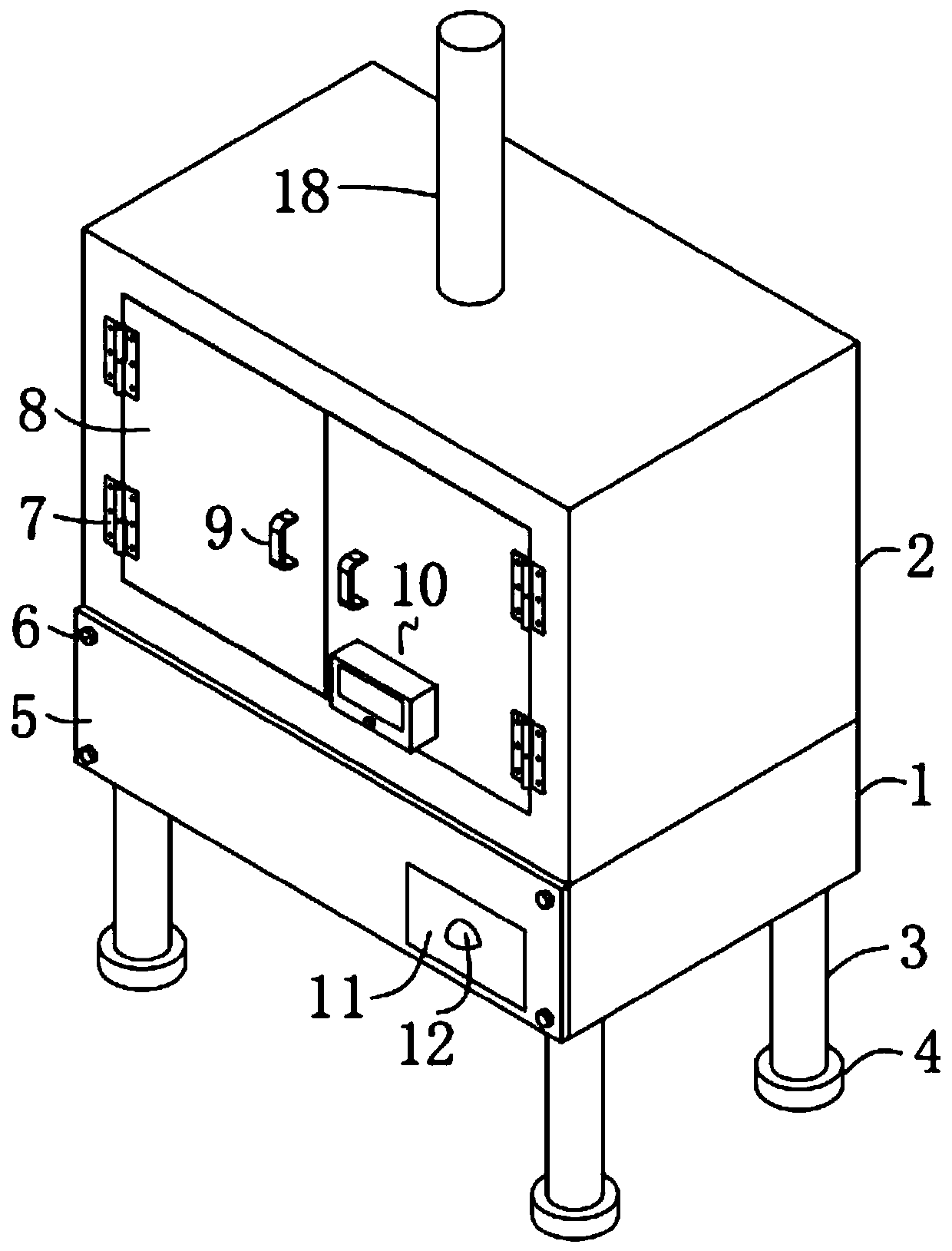
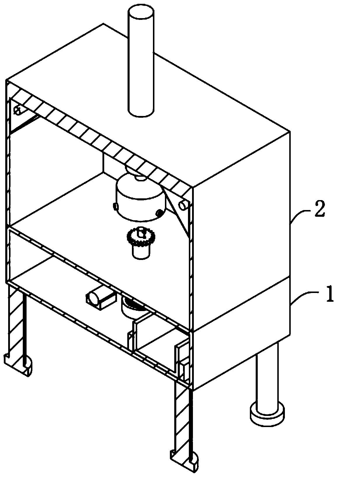
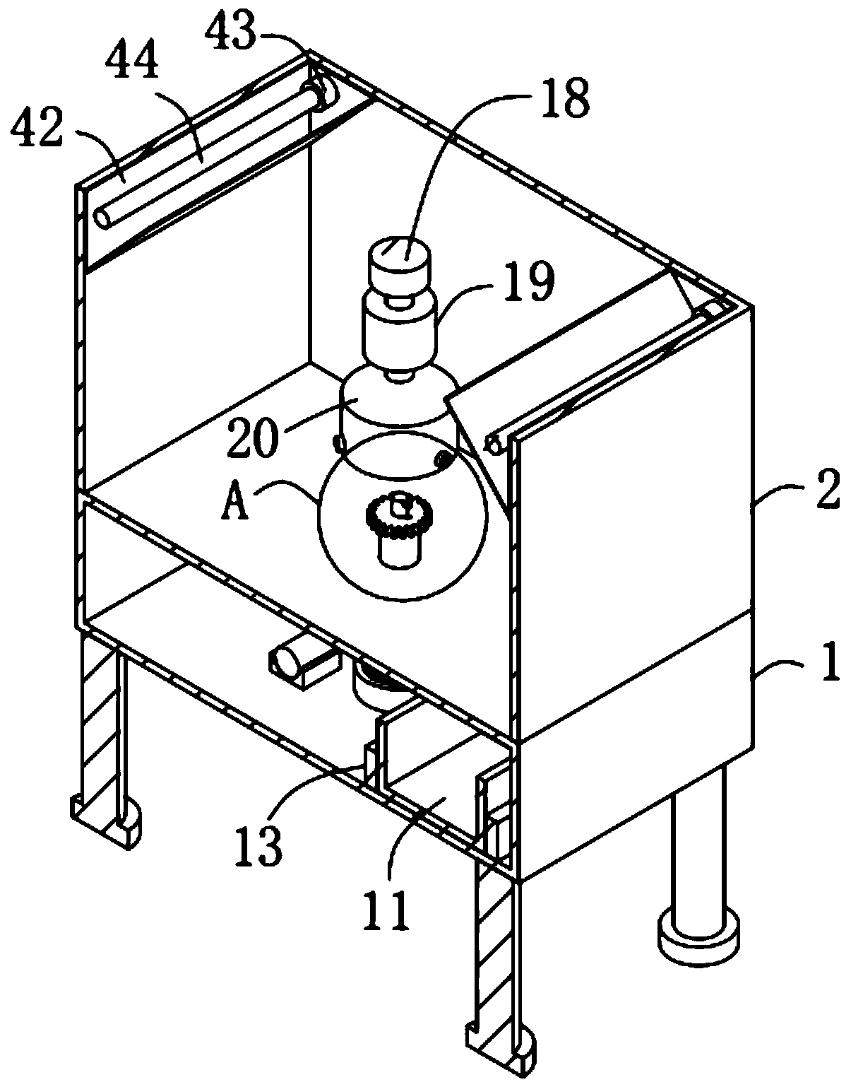
[0061] A device for chamfering sprocket teeth, such as Figure 1-2 , 5 and 10-11, including a support platform 1, a case 2 with an open bottom, two door panels 8, a sprocket tooth chamfering unit 14, a support unit 15 and a fixing unit 16, the support platform 1 The interior of the housing is a hollow structure, the casing 2 is fixedly installed on the table top of the support table 1, and an opening is opened in the center of the front wall of the casing 2, and the two door panels 8 are hinged by hinges 7 Inside the opening, the sprocket tooth chamfering unit 14 is installed on the top wall of the casing 2, the support unit 15 is installed on the table surface of the support table 1, and the support unit 15 is located directly below the sprocket tooth chamfering unit 14, the fixing unit 16 is installed through the table of the support table 1, and the fixing unit 16 is arranged in cooperation with the support unit 15;

[0062] Such as Figure 5 and 10 As shown in -11, the ...

Embodiment 2

[0087] The difference from Example 1 is that the upper surface of the support platform 1 is also provided with a protective layer, and the protective layer is prepared by the following method:

[0088] Take the following raw materials and weigh them by weight: 20 parts of epoxy resin, 10 parts of calcium carbonate powder, 10 parts of aluminum oxide powder, 13 parts of phenolic resin, 12 parts of polytetrafluoroethylene, 12 parts of acrylic emulsion, alcohol ester twelve parts 3 parts, BDMA 3 parts, high carbon alcohol fatty acid ester complex 2 parts and water 30 parts;

[0089] S1. Add the weighed acrylic emulsion, alcohol ester twelve, BDMA, higher alcohol fatty acid ester complex and water into the mixer and stir for 15 minutes at a stirring speed of 400r / min to prepare a mixed solution;

[0090] S2, adding epoxy resin, calcium carbonate powder, aluminum oxide powder, phenolic resin and polytetrafluoroethylene into a pulverizer for pulverization until the particle diameter ...

Embodiment 3

[0096] The difference with embodiment 2 is the preparation of protective layer, and its specific preparation method is as follows:

[0097] Take the following raw materials and weigh them by weight: 23 parts of epoxy resin, 12 parts of calcium carbonate powder, 11 parts of aluminum oxide powder, 15 parts of phenolic resin, 14 parts of polytetrafluoroethylene, 15 parts of acrylic emulsion, alcohol ester twelve 4 parts, BDMA 4 parts, high carbon alcohol fatty acid ester complex 3 parts and water 40 parts;

[0098] S1. Add the weighed acrylic emulsion, alcohol ester twelve, BDMA, higher alcohol fatty acid ester complex and water into the mixer and stir for 18min at a stirring speed of 500r / min to prepare a mixed solution;

[0099] S2, adding epoxy resin, calcium carbonate powder, aluminum oxide powder, phenolic resin and polytetrafluoroethylene into a pulverizer for pulverization until the particle diameter of the material is not greater than 100nm, and a mixed powder material is...


PUM


Abstract

The invention discloses equipment for chamfering of the sprocket part of a sprocket wheel. The equipment comprises a supporting table, a cover shell with an opening structure at the bottom, two door sheets, a sprocket wheel sprocket part chamfering unit, a supporting unit and a fixing unit, wherein the interior of the supporting table is of a hollow structure, the cover shell is fixedly arranged on the table surface of the supporting table, and an opening is formed in the middle of the front wall of the cover shell. According to the equipment, waste chips generated in the process of chamferingthe sprocket part of a sprocket wheel workpiece can be prevented from spreading the whole equipment and from being difficult to remove, the sprocket wheel workpiece can be fixed by using a machine, the operation is simple and trouble-saving, the production efficiency can be effectively improved, the illumination condition is good, the sight of an operator is guaranteed, the potential safety hazard is avoided, the function of storing objects is achieved, abnormal workpieces can be conveniently collected and stored, the technological personnel can analyze and process the abnormal workpieces, then the positive influence on the improvement on the production technology can be achieved, clearing is simple and convenient, and the large amount of waste chips can be prevented from adhering to thesurface of the supporting table.

Description

technical field [0001] The invention relates to the technical field of sprocket production, more specifically, it relates to a device for chamfering the teeth of a sprocket. Background technique [0002] A sprocket is a wheel with cog-type sprockets designed to engage precisely pitched blocks on a chain link or cable. Sprockets are widely used in chemical, textile machinery, escalators, wood processing, three-dimensional parking garages, agricultural machinery, food processing, instrumentation, petroleum and other industries for mechanical transmission. [0003] The sprocket needs to chamfer the teeth during production. The equipment used for chamfering the sprocket teeth in the prior art requires manual fixing of the sprocket workpiece to be processed. The fixing method is cumbersome and affects production. efficiency; secondly, the waste chips generated during the chamfering of the teeth of the sprocket workpiece cause the entire drilling machine to be everywhere and diff...

Claims


Application Information

Patent Timeline
IPC IPC(8): B23F19/10B23F23/06B23F23/12B23Q1/00B23Q11/00B23Q11/08B23Q17/24B05D3/02B05D7/24
CPCB05D3/0254B05D7/24B05D2301/00B05D2502/00B05D2504/00B05D2506/15B05D2518/00B23F19/10B23F23/06B23F23/12B23Q1/0009B23Q11/00B23Q11/08B23Q17/2404
Inventor 强春
Owner 常州盛天传动科技有限公司
Learn More