A high-sensitivity large-area laser ultrasound imaging method

A technology of laser ultrasound and imaging methods, which is applied in the fields of analyzing solids using sound waves/ultrasonic waves/infrasonic waves, material analysis using sound waves/ultrasonic waves/infrasonic waves, and material analysis through optical means, and can solve the problems of huge total data volume, optical or acoustic Problems such as increased reflection loss and high processing difficulty achieve the effect of simple image reconstruction algorithm, reduced multiple reflection attenuation, and fast data acquisition and transmission

Active Publication Date: 2022-03-18
南昌洋深电子科技有限公司
View PDF0 Cites 0 Cited by
  • Summary
  • Abstract
  • Description
  • Claims
  • Application Information

AI Technical Summary

Problems solved by technology

However, the above existing solutions all have the disadvantages of increased optical or acoustic reflection loss, reduced receiving area of ​​the acoustic detector, and high processing difficulty, resulting in reduced sensitivity of laser ultrasonic excitation and reception, and the mechanical scanning structure increases the volume and complexity of the system. sex
On the other hand, the above structure greatly limits the size of the imaging scanning area, whether it is optical scanning or mechanical scanning, which greatly reduces the real-time performance of the system, and usually collects laser ultrasonic signals during the entire depth propagation time period, resulting in total data It is difficult to achieve fast and large-area laser ultrasound imaging

Method used


Image

  • A high-sensitivity large-area laser ultrasound imaging method
  • A high-sensitivity large-area laser ultrasound imaging method
  • A high-sensitivity large-area laser ultrasound imaging method

Examples


Embodiment 1

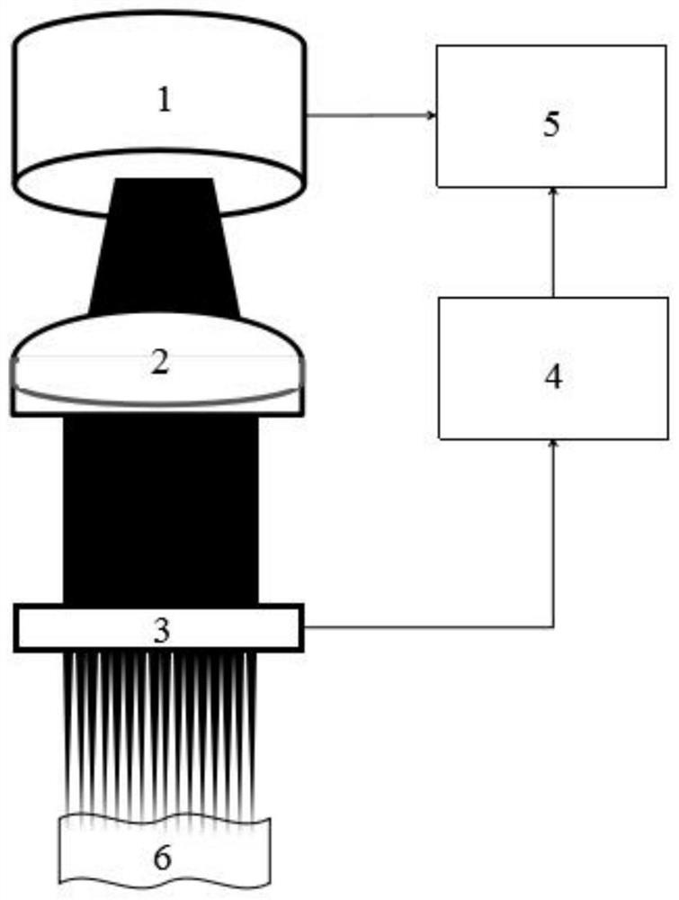
[0028] Example 1: See figure 1 ,like figure 1 A high-sensitivity large-area laser ultrasonic imaging system shown includes 1. a light source, 2. a collimator lens, 3. a microlens array, 4. a signal preprocessing module, 5. a computer, and 6. a sample to be tested.

[0029] A collimating lens 2 and a microlens array 3 are placed in sequence directly under the light source 1 ; the measured sample 6 is placed under the microlens array 3 .

[0030] The microlens array 3 , the signal preprocessing module 4 and the computer 5 are electrically connected in sequence; the light source 1 and the computer 5 are electrically connected in sequence.

[0031] Further, the light source 1 is a wavelength-tunable OPO laser (GWU, model versaScan / 120), with an optical pulse width of 10 ns, an operating wavelength of 410-2500 nm, and a maximum single pulse energy of 30 mJ; the array size of the microlens array 3 is 10mm*10mm, the diameter of the microlens array is 250um, the radius of curvature ...

Embodiment 2

[0034] The structure of this embodiment is similar to that of Embodiment 1, except that the light source 1 is a pulsed laser diode (Laser Components, model 905D4S16C), with an optical pulse width of 100 ns, an operating wavelength of 905 nm, and a peak power of 140 W.

[0035] The present invention also provides a method for imaging using the above-mentioned device, comprising the following steps:

[0036] S1: The light source 1 emits a pulsed or modulated light beam, which is collimated by the collimator lens 2, and then micro-focused and irradiated by the microlens array 3 on the tested sample 6 to generate a laser ultrasonic signal;

[0037] S2: The laser ultrasonic signal is received by each microlens array element of the microlens array 3 in the back mode, and after the signal preprocessing module 4, the extreme value of the laser ultrasonic signal is read and stored in the computer 6 by row and column addressing;

[0038] S3: The extreme value of the laser ultrasonic sig...


PUM


Abstract

The invention discloses a high-sensitivity large-area laser ultrasonic imaging method, which can realize fast laser ultrasonic imaging in a back mode with simple structure, high sensitivity and large field of view. In the present invention, the microlens array made of piezoelectric material with high optical transmittance is selected as the laser micro-focusing unit and the ultrasonic signal receiving unit at the same time, and the coaxial, confocal and integrated structure of the optical and acoustic paths is cleverly realized. Eliminates the optical or acoustic multiple reflection excitation or reception structure, effectively improves the efficiency of laser ultrasonic excitation, the sensitivity of reception and the signal-to-noise ratio, and it is easier to realize the miniaturization and large-area imaging of laser ultrasonic lenses, which is expected to be applied In biometric identification, medical subcutaneous vascular imaging, non-destructive testing of materials and other fields.

Description

technical field [0001] The invention relates to an imaging method, in particular to a high-sensitivity large-area laser ultrasonic imaging method, which is suitable for the fields of biological blood vessel imaging and identification, non-destructive flaw detection of material sub-surface and the like. Background technique [0002] Laser ultrasonic imaging technology is a new type of non-destructive testing technology that can achieve high-resolution medical or industrial detection at the level of hundreds of microns to tens of nanometers. In the microscopic imaging mode, the resolution is higher and the required laser energy is lower. As low as the nano-focus level, the optical excitation path and the acoustic detection path usually require a coaxial confocal structure to improve the laser ultrasonic excitation and detection efficiency. [0003] The commonly used scheme is to add a light-transmitting and anti-acoustic (or sound-transmitting and reflective) element in the op...

Claims


Application Information

Patent Timeline
Patent Type & Authority Patents(China)
IPC IPC(8): G01N21/17G01N21/01G01N29/06G01N29/24
CPCG01N21/1702G01N21/01G01N29/0681G01N29/2418G01N2021/1708
Inventor 曾吕明纪轩荣吴俊伟邓丽军朴忠烈丁宇周阳
Owner 南昌洋深电子科技有限公司
Why Eureka
Try Eureka