A fuel cell integrated diffusion layer and its preparation method and application
A fuel cell and gas diffusion layer technology, which is applied in the field of fuel cell gas diffusion layers, can solve the problems of low conductivity of asphalt-based CFs, and achieve the effects of reducing preparation cost, facilitating material distribution, and overcoming brittleness.
- Summary
- Abstract
- Description
- Claims
- Application Information
AI Technical Summary
Problems solved by technology
Method used
Image
Examples
Embodiment 1
[0035] Example 1 Preparation of one-piece diffusion layer
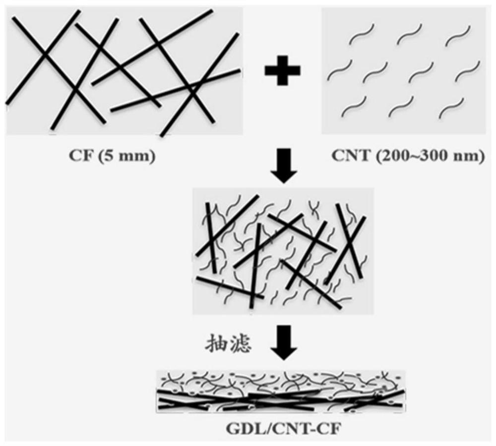
[0036] Weigh 45mg of multi-walled carbon nanotubes in a 100mL high beaker, add 45mL nitrogen methyl pyrrolidone (NMP) as a dispersant (about 1mg mL -1 ), ultrasonicated for 1 h, dispersed with a high-speed disperser for 3 min at a speed of 20,000 rmp, as solution A; weighed 15 mg of carbon fiber, added 45 ml of NMP (1 / 3 mg mL -1 ), sonicated for 30 min, as solution B; poured A into solution B, added 6 mg of PTFE slurry (10%), sonicated in an ultrasonic cleaner for 1 h, stirred at 20,000 rpm for 3 min, and then used suction filtration prepared in advance The device was quickly filtered to form a membrane, and the filter membrane was a PTFE membrane (45 μm). Then vacuum drying at 130 °C, and finally the preformed diffusion layer was placed in a high-temperature tube furnace at 350 °C for 3 hours, which is a new type of integrated diffusion layer (GDL / CNT-CF). The schematic diagram of the preparation method is as follo...
Embodiment 2
[0038] Preparation of GDL / Toray-060H: Take commercial Toray-060H carbon paper as the anode and cathode diffusion layer substrate, take an appropriate amount of polytetrafluoroethylene (PTFE) and carbon powder (XC-72), stir evenly to form a mixed slurry, and then pass Coating method Coating on the base layer to prepare the microporous layer. The loadings of XC-72R and PTFE in the anode / cathode microporous layer were 2 mg cm, respectively -2 , 10wt% and 2mgcm -2 , 40wt%.
Embodiment 3
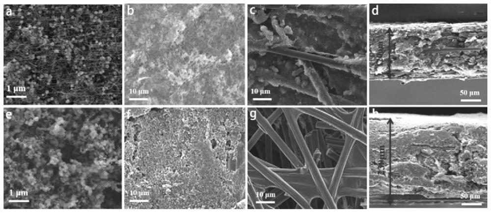
[0040] The JSM-6360LV field emission scanning electron microscope (SEM) of JOEL company was used to characterize the structure and microscopic morphology of the diffusion layer prepared in Example 1, and compared with the commercial diffusion layer in Example 2. The comparison results are as follows image 3 shown.
[0041] It can be seen from the front micro-morphology that the carbon nanotubes are very uniformly dispersed and scattered, and the PTFE pellets are evenly embedded on the carbon nanotubes; Some larger holes are formed between the carbon fibers; from the cross-sectional comparison diagram, the thickness of the new GDL is only 120 nm, which is about 1 / 2 of the commercial diffusion layer. More carbon nanotubes can directly act as a microporous layer, in contact with the catalytic layer, while the bottom has more carbon fibers, and the pore structure gradually increases. The large pores are conducive to the transport of water, while the small hydrophobic pores keep t...
PUM
| Property | Measurement | Unit |
|---|---|---|
| length | aaaaa | aaaaa |
| thickness | aaaaa | aaaaa |
| thickness | aaaaa | aaaaa |
Abstract
Description
Claims
Application Information
 - R&D
- Intellectual Property
- Life Sciences
- Materials
- Tech Scout
- Unparalleled Data Quality
- Higher Quality Content
- 60% Fewer Hallucinations
Browse by: Latest US Patents, China's latest patents, Technical Efficacy Thesaurus, Application Domain, Technology Topic, Popular Technical Reports.
© 2025 PatSnap. All rights reserved.Legal|Privacy policy|Modern Slavery Act Transparency Statement|Sitemap|About US| Contact US: help@patsnap.com


