
Dry desulfurization, denitration and dust removal device and method for low-sulfur flue gas in cement kiln tail

A dry desulfurization, denitration and dust removal technology, applied in separation methods, chemical instruments and methods, gas treatment, etc., can solve the problems of high operation and maintenance costs, high fire risks, and technical difficulties of denitrification devices, and achieve obvious technical and Economical application advantages, low overall investment and operating costs, and the effect of reducing filter area

Pending Publication Date: 2020-01-10
FUJIAN LONGKING DSDN ENGINEERING CO LTD
View PDF3 Cites 9 Cited by
  • Summary
  • Abstract
  • Description
  • Claims
  • Application Information

AI Technical Summary

Problems solved by technology

However, the above-mentioned technical solution has the following deficiencies: (1) problems of catalyst poisoning and clogging, and low denitrification efficiency; in this technical solution, the flue gas directly enters the SCR device, which belongs to the high-dust arrangement, and the temperature of the flue gas is high and the dust content is high. It is easy to cause catalyst poisoning, deactivation and blockage, short service life, and high operation and maintenance costs of denitrification devices.
(2) Blockage and corrosion of downstream equipment; since the waste heat power generation boiler and other facilities are arranged downstream of the SCR denitrification device here, if the ammonia escape control of the SCR denitrification system is not properly controlled, it is easy to cause blockage, corrosion and thermal efficiency reduction of the cooling device. question
(3) Spraying desulfurizer into the intake pipe of the bag filter has low efficiency and unstable desulfurization effect. It is only suitable for low-sulfur and low-flue gas projects with loose emission indicators, and cannot meet ultra-low emission requirements.
However, the above-mentioned technical solutions have the following disadvantages: (1) the use of low-temperature catalysts has no actual operating performance in China, and there are very few manufacturers that can produce them, which will inevitably lead to high prices, high investment costs, and great technical difficulties
(3) When using wet desulfurization, there must be a wastewater treatment system specially designed to deal with highly polluted wet desulfurization wastewater; SO cannot be effectively removed 3 Submicron aerosol particles; after desulfurization, white plume, blue plume, and chimney rain are common at the chimney mouth; the flue gas is saturated wet flue gas, which is strongly acidic, and the desulfurization tower, flue, and chimney need to be anti-corrosion, and the investment and High operating costs, high risk of fire during construction and maintenance
However, the above-mentioned technical solutions have the following disadvantages: (1) the use of low-temperature catalysts has no actual operating performance in China, and there are very few manufacturers that can produce them, which will inevitably lead to high prices, high investment costs, and great technical difficulties
(2) Compared with medium and high temperature catalysts, the catalyst volume increases and the pressure loss is large

Method used


Image

  • Dry desulfurization, denitration and dust removal device and method for low-sulfur flue gas in cement kiln tail

Examples


Embodiment 1

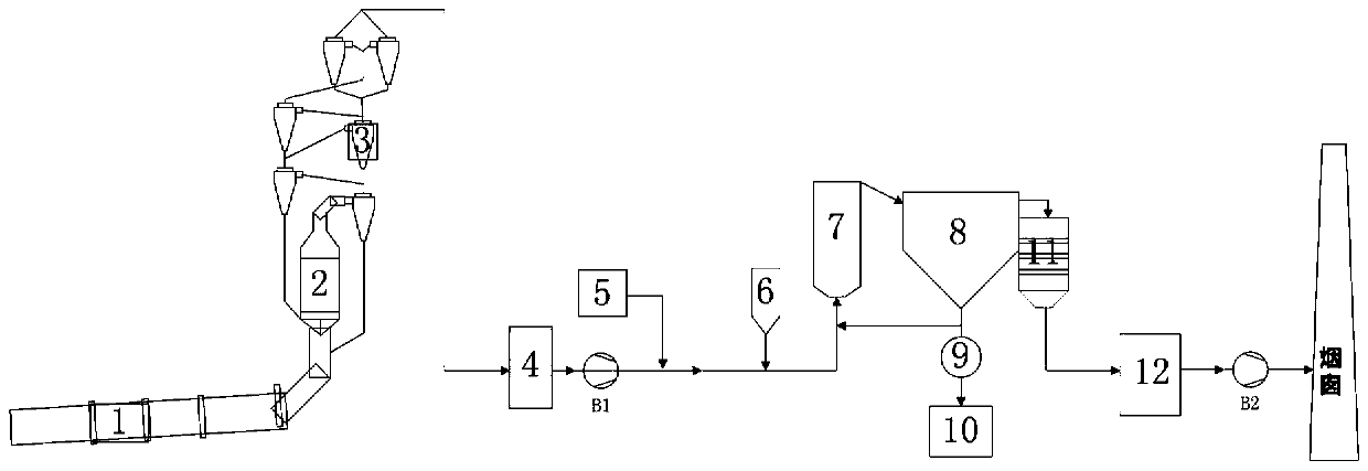
[0076] The schematic diagram of the structure of the low-sulfur flue gas dry desulfurization, denitrification and dust removal device at the cement kiln tail provided by the embodiment of the present invention can be found in figure 1 As shown; among them, 1 is a cement kiln, 2 is a calciner, 3 is a suspension preheater, 4 is a waste heat boiler, B1 is a high-temperature fan, 5 is a raw meal mill, 6 is a desulfurizer warehouse, and 7 is a low-density low-bed Circulating fluidized bed dry desulfurization tower with no water spraying on the first floor, 8 is a bag filter, 9 is a pneumatic conveying warehouse pump, 10 is a raw material storage, 11 is a medium temperature SCR denitrification device, 12 is a waste heat boiler, and B2 is an induced draft fan.

[0077] The connection relationship of the dry desulfurization, denitrification and dust removal device is specifically: the gas outlet of the cement kiln (1) is connected to the air inlet of the calciner (2), and the gas outlet ...


PUM


Abstract

The invention relates to a dry desulfurization, denitration and dust removal device for low-sulfur flue gas in cement kiln tail. The dry desulfurization, denitration and dust removal device includes acement kiln, a decomposing furnace, a suspension preheater, a cooling device, a desulfurization tower, a dust remover and a medium-temperature SCR denitration device, wherein the cement kiln, the decomposing furnace, the suspension preheater and the cooling device are successively connected, an air inlet pipeline of the desulfurization tower is connected with a flue gas outlet of the cooling device, and the desulfurization tower is a circulating fluidized bed dry desulfurization tower with the low density, a low bed and no water spraying; the air inlet pipeline is provided with a high-temperature fan, and connected with a raw mill, a desulfurizer bin and a smoke dust return device; a flue gas inlet of the dust remover is connected with a flue gas outlet of the desulfurization tower, and aby-product outlet of the dust remover communicates with the air inlet pipeline through the smoke dust return device, and is connected with a raw material warehouse through a by-product conveying device; and a flue gas inlet of the medium-temperature SCR denitration device is connected with a flue gas outlet of the dust remover, an air outlet pipeline of the medium-temperature SCR denitration device is successively provided with a waste heat boiler and an induced draft fan, and discharges purified gas through a chimney. According to the dry desulfurization, denitration and dust removal device,synergistic removal of multi-component contaminants can be achieved while high-efficiency desulfurization, denitration and dust removal are achieved, corrosion prevention is not needed, zero waste water discharge and transparent chimney discharge are achieved, and meanwhile long-term stable operation can be achieved.

Description

technical field [0001] The invention relates to the technical field of desulfurization and denitrification treatment, and more specifically relates to a dry-process desulfurization, denitrification and dust removal device and method for low-sulfur flue gas at the tail end of a cement kiln. Background technique [0002] Cement kilns are the main source of flue gas pollutant emissions in the cement industry. The combustion of coal powder and calcination of clinker in cement kilns will produce a large amount of flue gas, accompanied by dust particles, SO 2 , NO x and pollutants such as fluoride. The use of traditional raw fuels will bring trace amounts of heavy metal elements into the cement kiln, and the application of alternative raw fuels and co-processing of waste will also introduce a certain amount of heavy metal elements. Under a certain concentration limit, most of the heavy metal elements will be solidified in the cement clinker, and the cement hydration products and...

Claims


Application Information

Patent Timeline
Patent Type & Authority Applications(China)
IPC IPC(8): B01D53/75B01D53/81B01D53/50B01D53/86B01D53/56B01D46/00
CPCB01D53/75B01D53/81B01D53/508B01D53/8628B01D53/56B01D46/00B01D2258/0283B01D2257/2045B01D2257/2047B01D2257/206B01D2257/60B01D2257/40
Inventor 李晓峰詹威全郭志航陈树发林春源黄彬杰江倩倩江素萍张原王建春
Owner FUJIAN LONGKING DSDN ENGINEERING CO LTD
Learn More