Flue gas desulfurization system and method using calcium carbide slag/slurry

A desulfurization system, calcium carbide slag technology, applied in separation methods, chemical instruments and methods, calcium/strontium/barium sulfate, etc., can solve the problem that calcium sulfite cannot be effectively dehydrated, sulfur dioxide emissions are not up to standard, and the pH value of tower kettle slurry rises Advanced problems, to avoid environmental risks, ensure absorption, improve the effect of purity

Active Publication Date: 2020-02-21
HUNAN HENGGUANG TECH
View PDF6 Cites 3 Cited by
  • Summary
  • Abstract
  • Description
  • Claims
  • Application Information

AI Technical Summary

Problems solved by technology

After the pH of the desulfurization slurry rises, it will first cause carbon dioxide in the flue gas to form calcium carbonate with calcium hydroxide, and the excess calcium hydroxide will cause the pH value of the slurry in the tower to rise, resulting in the inability of calcium sulfite to be effectively absorbed under high pH conditions. Oxidized to calcium sulfate, calcium sulfite cannot be effectively dehydrated, and the calcium sulfite cement plant with high water content after dehydration cannot be consumed; if less calcium carbide slag desulfurizer is added, the pH of the desulfurization slurry is low, and sulfur dioxide cannot be combined with calcium hydroxide to produce calcium sulfite , the emission of sulfur dioxide is not up to the standard

Method used


Image

  • Flue gas desulfurization system and method using calcium carbide slag/slurry

Examples


Embodiment 1

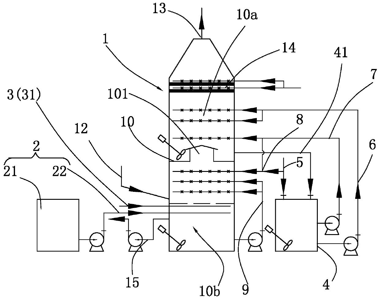
[0044] attached figure 1 It is a schematic diagram of the calcium carbide slag / pulp flue gas desulfurization system provided by the present invention. The calcium carbide slag / slurry flue gas desulfurization system provided by the present invention includes a desulfurization tower 1, a sulfuric acid delivery device 2, an oxidation air delivery device 3, a desulfurization slurry tank 4, a calcium carbide slurry supplementary pipe 5, a first spray device 6, a second spray Showering device 7, third spraying device 8, fourth spraying device 9, partition 10. The partition 10 divides the reaction space in the desulfurization tower into two parts, the sulfur dioxide absorption zone 10a located on the upper part of the partition 10 and the calcium sulfite oxidation zone 10b located on the lower part of the partition 10 .

[0045] The desulfurization tower 1 has a cylindrical structure, with a flue gas pipe 12 at the bottom and an exhaust pipe 13 at the top. The flue gas pipe 12 is us...


PUM


Abstract

The invention discloses a flue gas desulfurization system using calcium carbide slag/slurry. The flue gas desulfurization system comprises a desulfurization tower, a flue gas pipeline, an exhaust pipe, a first conveying pipe entering slurry at the bottom of the desulfurization tower and used for conveying waste sulfuric acid, a second conveying pipe entering the slurry at the bottom of the desulfurization tower and used for convey oxidizing air, a desulfurization slurry tank, a calcium carbide slurry supplementing pipe used for adding calcium carbide slurry into the desulfurization slurry tank, a third conveying pipe used for conveying slurry in the desulfurization tower to the desulfurization slurry tank, a first spraying device and a second spraying device both connected with the desulfurization slurry tank and used for conveying desulfurization slurry to the desulfurization tower for spray absorption of sulfur dioxide, a third spraying device connected with the liquid conveying pipeof the second spraying device, a fourth spraying device arranged at the inner lower part of the desulfurization tower and used for promoting oxidation of calcium sulfite, a partition plate arranged in the desulfurization tower and provided with a riser, and a demisting device arranged at the top of the desulfurization tower. The carbide slag/slurry flue gas desulfurization system is high in desulfurization efficiency and high in purity of generated calcium sulfate.

Description

technical field [0001] The invention relates to the technical field of flue gas desulfurization, in particular to a calcium carbide slag / pulp flue gas desulfurization system and method. Background technique [0002] Existing flue gas desulfurization methods include limestone-gypsum wet method, rotary spray drying method, metal oxide method, flue gas circulating fluidized bed method and activated carbon method, among which wet desulfurization is more commonly used in industry. Wet desulfurization is to use lime, calcium carbide slag / slurry, limestone, etc. as desulfurizers, and make the desulfurizer into a slurry, and the flue gas is in countercurrent contact with the slurry in the spray tower, and the sulfur dioxide in the flue gas is oxidized and absorbed by the desulfurizer to form CaSO 4 , so as to achieve the purpose of flue gas desulfurization. [0003] In the existing wet desulfurization method, in order to improve the absorption efficiency of sulfur dioxide, the pH v...

Claims


Application Information

Patent Timeline
Patent Type & Authority Applications(China)
IPC IPC(8): B01D53/50B01D53/75B01D53/80C01F11/46
CPCB01D53/502B01D53/504B01D53/75B01D53/80C01F11/464B01D2258/0283
Inventor 易重庆赵利启唐络络程米亮杨长丕
Owner HUNAN HENGGUANG TECH
Why Eureka
Try Eureka