Time correlation Raman-fluorescence lifetime spectrometer based on SPAD

A technology of fluorescence lifetime and spectrometer, which is applied in the field of Raman-fluorescence lifetime spectrometer, can solve the problems of low Raman signal-to-noise ratio, low measurement rate, complex system, etc., to improve measurement efficiency, increase signal-to-noise ratio, multi-channel Quantity effect

Pending Publication Date: 2020-02-25
陈昊昌 +1
View PDF8 Cites 5 Cited by
  • Summary
  • Abstract
  • Description
  • Claims
  • Application Information

AI Technical Summary

Problems solved by technology

[0014] In order to overcome the phenomenon that the existing Raman spectrometer is susceptible to the interference of sample fluorescence and background noise, which causes the signal-to-noise ratio of Raman signal to be low, and the important...

Method used


Image

  • Time correlation Raman-fluorescence lifetime spectrometer based on SPAD
  • Time correlation Raman-fluorescence lifetime spectrometer based on SPAD
  • Time correlation Raman-fluorescence lifetime spectrometer based on SPAD

Examples


Embodiment 1

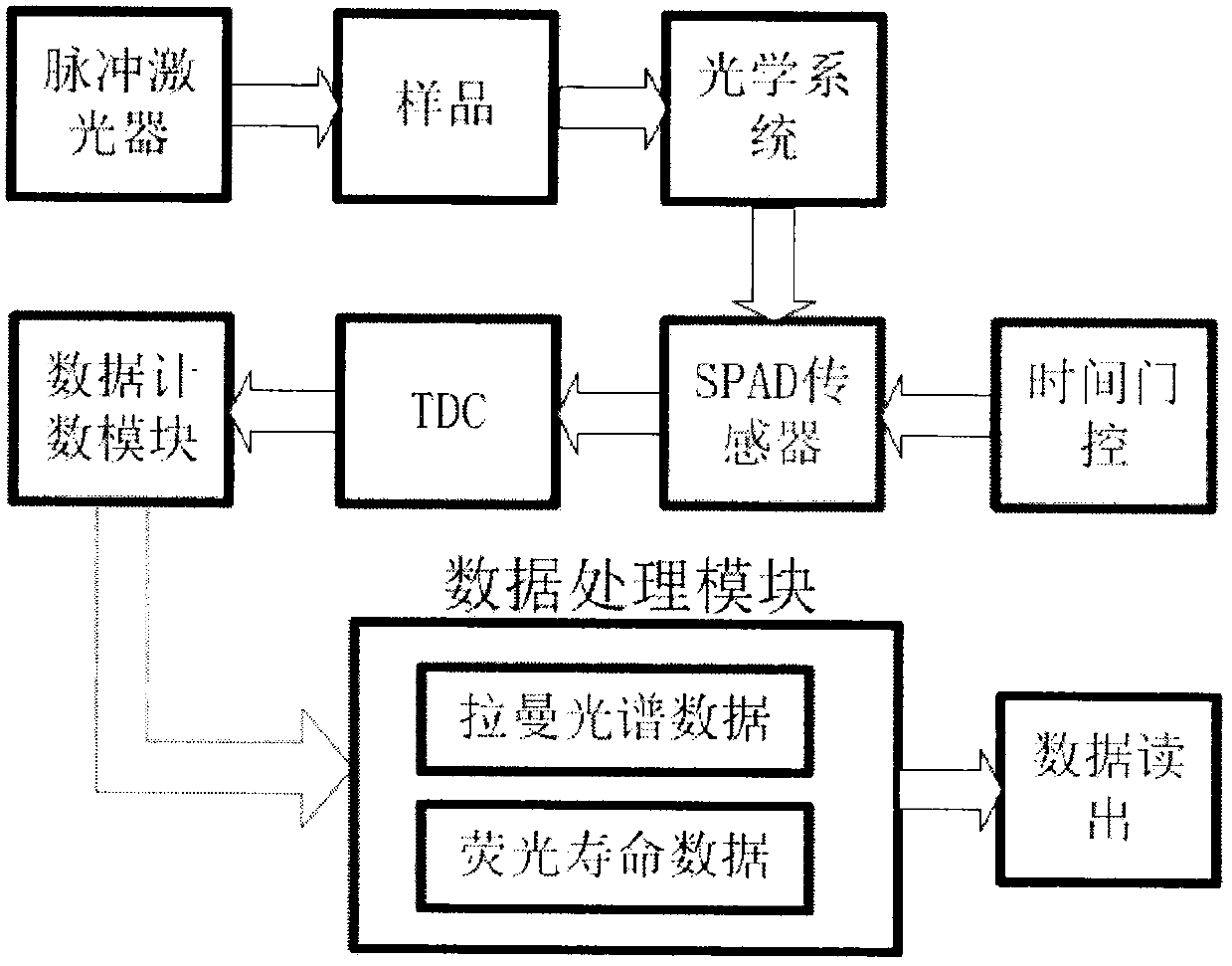
[0030] Such as figure 2 As shown, a time-correlated fluorescence suppression Raman spectroscopy-fluorescence lifetime instrument based on a SPAD sensor is mainly composed of a pulse laser, an optical system, a time gating circuit, a SPAD array sensor, a TDC module, a data counting module, a data processing module and corresponding software and user interface components.

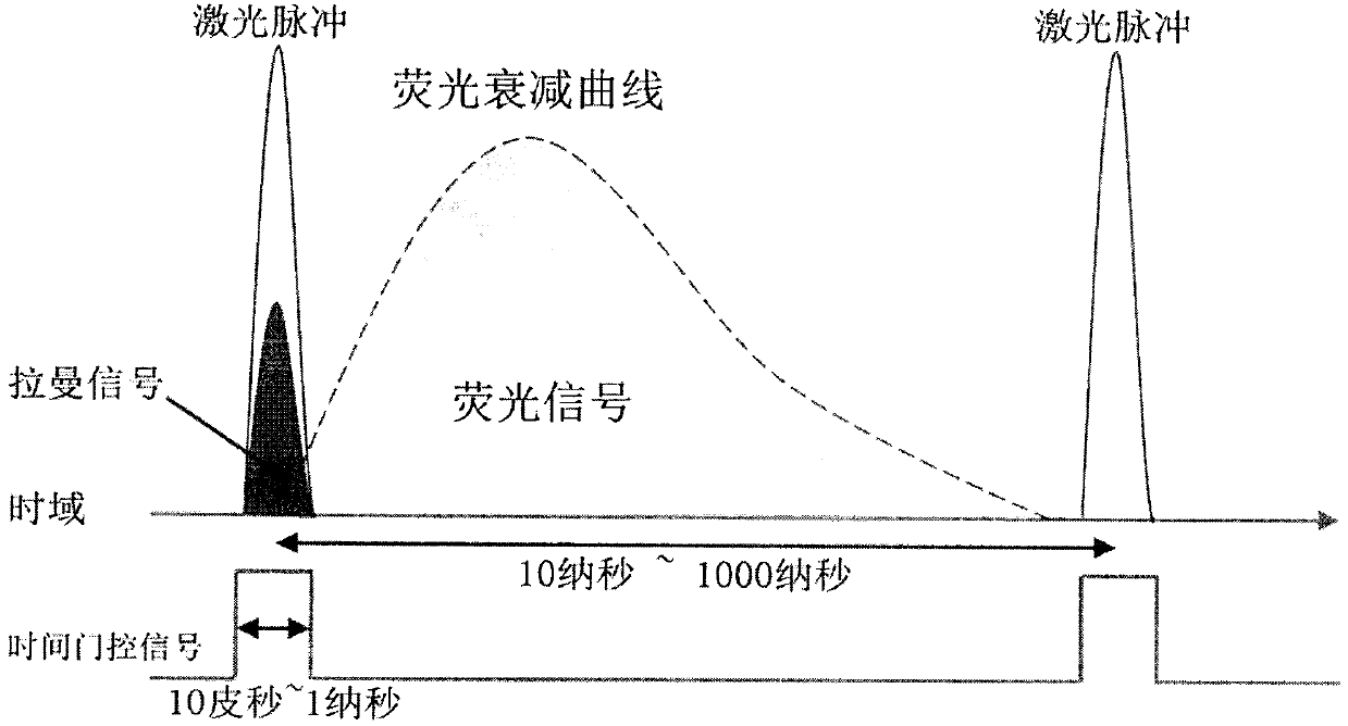
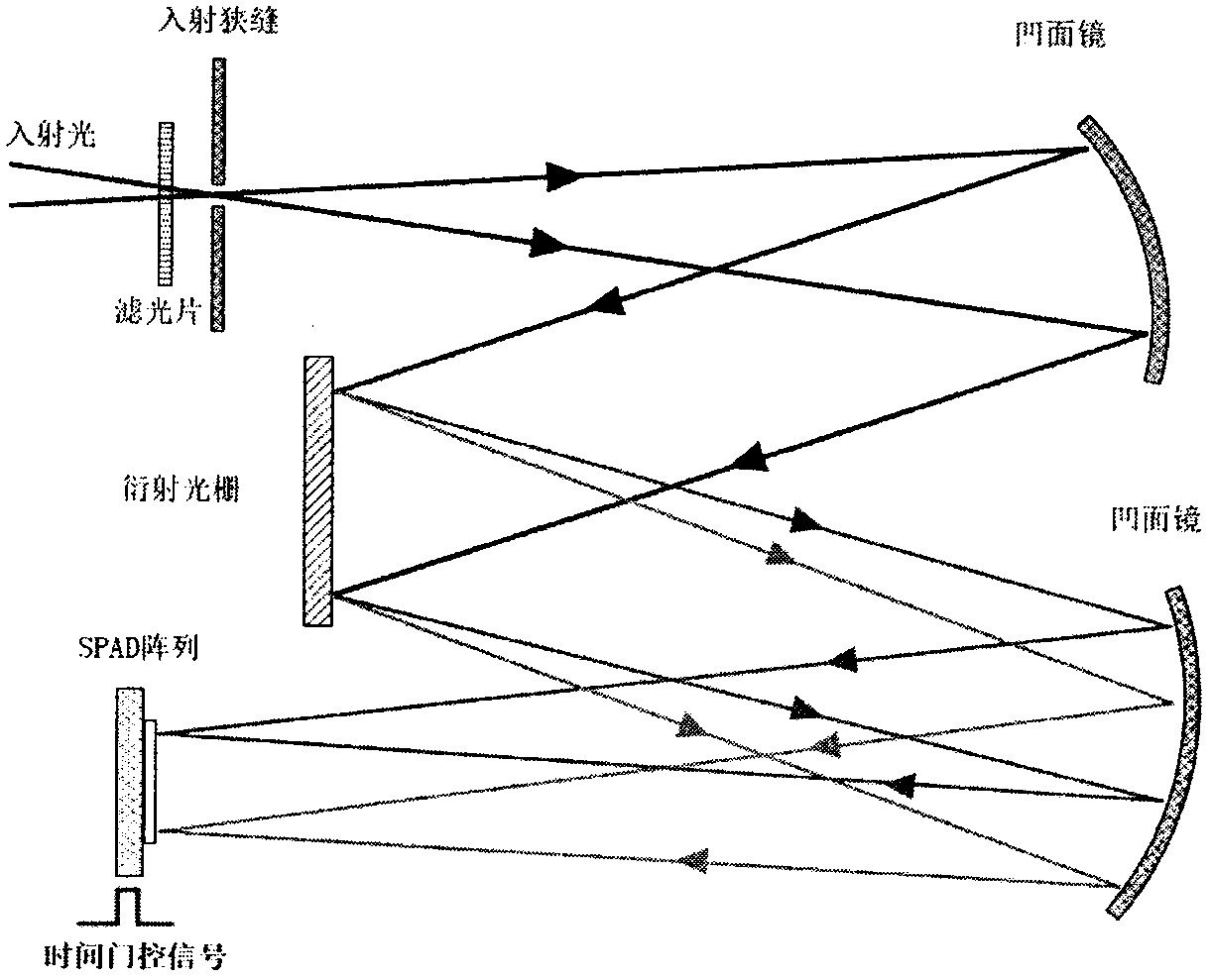
[0031] The laser light source usually uses a pulsed laser with a pulse width of less than 100 picoseconds in the visible light band as the excitation light source. It is driven by the laser driver and outputs the reference clock to the TDC and the time gating circuit. The optical system is mainly composed of various filters, lenses, mirrors, slits and diffraction gratings. The system construction varies according to the instrument configuration parameters, such as image 3 is a commonly used Raman spectrometer optical system, but is not limited to the architecture of the optical system. When a sample is ...

Embodiment 2

[0038] This embodiment is similar to Embodiment 1. The difference is that only the time-gated circuit is used instead of the TDC module to simplify the system, so it only has the function of a Raman spectrometer, and its system architecture is as follows Figure 5 shown. Therefore, finer control of the gating circuit is required to achieve the ideal fluorescence background suppression effect. Therefore, the gating window needs to cover only the time range of the Raman signal and completely ignore other time signals such as fluorescence and background noise. This method cannot obtain purer Raman signals and other additional fluorescence spectral information as in Example 1, but can still achieve an obvious fluorescence suppression effect and increase the detection speed of Raman spectroscopy. Such as Image 6 As shown, only one-dimensional counter structure is required in the data counting module and the function of the data processing module will be greatly simplified, so t...

Embodiment 3

[0040] In this implementation example, Raman imaging and fluorescence lifetime imaging functions are realized by adding a scanning module (such as a two-dimensional scanning sample stage driven by a high-precision stepping motor). Through point-by-point scanning and sampling of different positions of the sample. In this way, each pixel in the image contains the complete Raman spectrum and the fluorescence decay curve information of each spectral segment. Then according to the parameters extracted from these information, a pseudo-color image is generated to intuitively display the spatial distribution of various parameters in the sample. For example, imaging using parameters such as intensity, position, and half-maximum width of Raman peaks can obtain spatial distributions such as material concentration, molecular structure, and crystallinity. The spatial distribution of fluorescence luminosity and lifetime in different spectral bands can be obtained using fluorescence decay c...


PUM


Abstract

The invention discloses a Raman-fluorescence lifetime spectrometer based on a single phototn avalanche diode (SPAD) array sensor, a picosecond-level time gating circuit, a high-precision time-to-digital converter (TDC) and a high-speed fluorescence lifetime algorithm. An SPAD array is used as a Raman spectrum and fluorescence signal detector, and the picosecond-level time gating circuit is used for filtering noise to improve the signal-to-noise ratio and the detection efficiency; and the time domain information of the Raman spectrum and a fluorescence attenuation curve is recorded through TDC,and a fluorescence lifetime algorithm is combined to rapidly calculate the fluorescence lifetime. A real and pure Raman signal is obtained by utilizing a fluorescence background inhibition algorithm,so that the detection capability and the detection efficiency of Raman spectrum and fluorescence lifetime are improved. According to the invention, Raman spectrum, fluorescence spectrum and fluorescence lifetime measurement and calculation can be achieved at the same time by using one set of system, and Raman spectrum, fluorescence spectrum and fluorescence lifetime measurement and calculation can be obtained respectively, so that the Raman-fluorescence lifetime spectrometer has obvious technical advantages compared with a traditional method.

Description

technical field [0001] The present invention relates to a design principle and implementation method of a SPAD-based time-correlated Raman-fluorescence lifetime spectrometer, in particular to a single-photon avalanche diode (SPAD) array detector, a picosecond-level gating circuit, and a high-precision time-to-digital converter (TDC), and Raman-FLIS with high-speed fluorescence lifetime and background suppression algorithms. [0002] technical background [0003] Raman spectroscopy is a method based on the characteristics of the interaction between light and matter, using Raman scattering for non-destructive and label-free detection, which can analyze the structural composition of almost all forms of materials at the molecular level (SMITH, E. & DENT, G. 2013. Modern Raman spectroscopy: a practical approach, John Wiley & Sons.). Due to its characteristics of non-contact, non-destructive, short detection time, small amount of sample required and no preparation, it has been wid...

Claims


Application Information

Patent Timeline
IPC IPC(8): G01N21/65G01N21/64
CPCG01N21/65G01N21/64G01N2021/6495
Inventor 陈昊昌李大卫
Owner 陈昊昌
Why Eureka
Try Eureka