Gradient waste heat recovery and direct reduction system and method for iron-containing metallurgical slag particles

A waste heat recovery system and waste heat recovery technology, applied in the direction of improving process efficiency and reducing gas emissions, can solve the problems of low waste heat recovery efficiency and poor economy of metallurgical slag particles

Active Publication Date: 2020-03-27
QINGDAO TECHNOLOGICAL UNIVERSITY
View PDF7 Cites 6 Cited by
  • Summary
  • Abstract
  • Description
  • Claims
  • Application Information

AI Technical Summary

Problems solved by technology

[0006] The purpose of the present invention is to overcome the shortcomings of the above-mentioned prior art, and provide a cascade waste heat recovery and direct reduction system and method for iron-containing metallurgical slag particles, w

Method used


Image

  • Gradient waste heat recovery and direct reduction system and method for iron-containing metallurgical slag particles
  • Gradient waste heat recovery and direct reduction system and method for iron-containing metallurgical slag particles
  • Gradient waste heat recovery and direct reduction system and method for iron-containing metallurgical slag particles

Examples


Embodiment 1

[0147] The slag used in the implementation of the present invention comes from the slag discharge of a flash smelting furnace of a domestic copper smelting enterprise, and its main components are as shown in Table 1.

[0148] Method A:

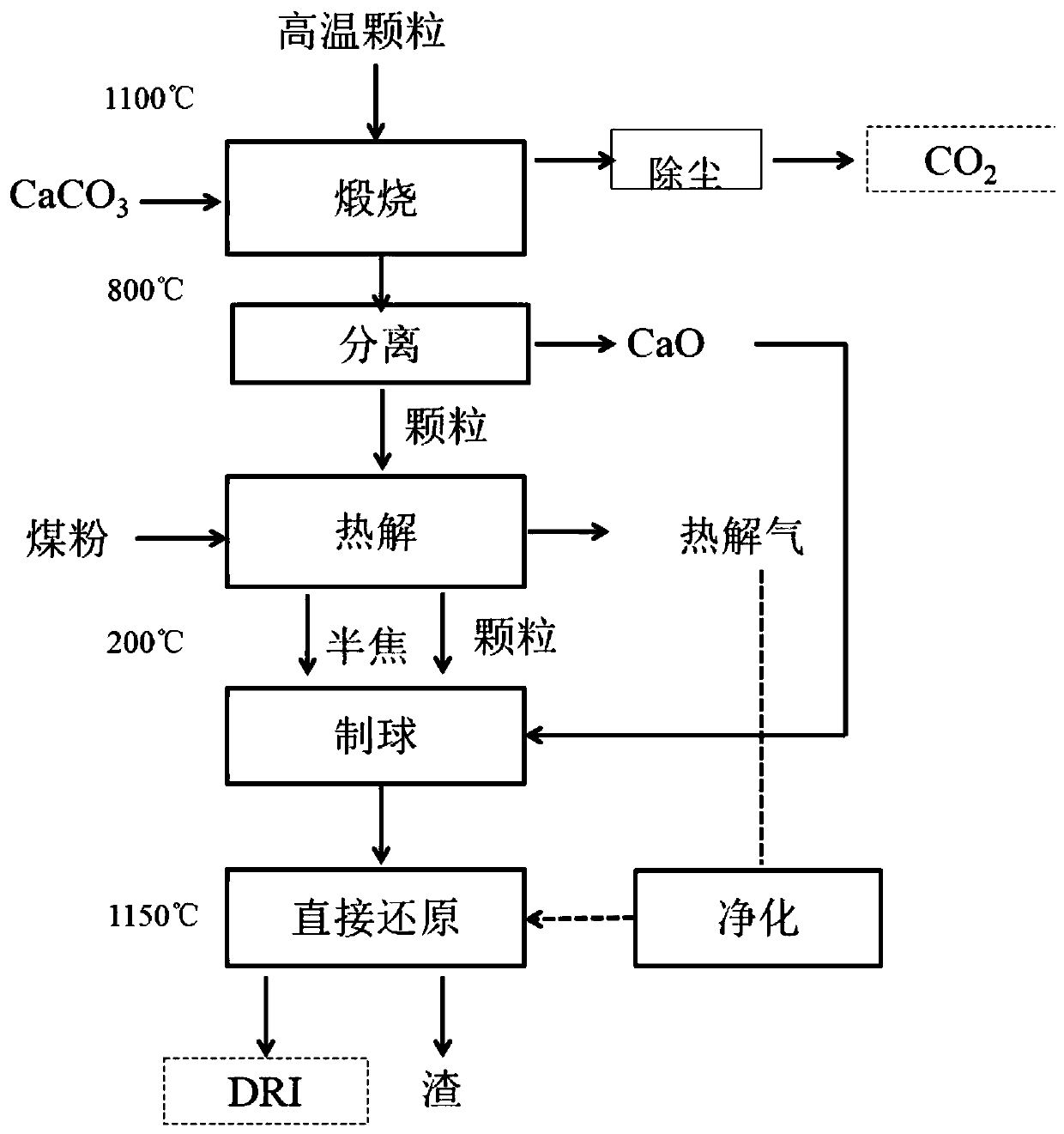
[0149] A method for cascaded waste heat recovery and direct reduction of iron-containing metallurgical slag, the process flow chart of mode A is as follows figure 1 As shown, the process mainly consists of four steps: calcination, pyrolysis, pelletizing and direct reduction. The main raw materials of the calciner are limestone, CaCO 3 The content is 92%. The main raw material of the pyrolysis furnace is pulverized coal, and the type is lignite. The industrial analysis is shown in Table 2. The calciner and pyrolysis furnace are both fixed beds. In the two devices, limestone and coal powder need to be dried and ground to below 100 mesh before entering. The products of the pyrolysis furnace are pyrolysis gas and semi-coke. The components of t...

Embodiment 2

[0185] Method A:

[0186] A cascade waste heat recovery and direct reduction system for iron-containing metallurgical slag particles, adopting mode A, and the system structure is the same as that of embodiment 1 mode A, and the method for cascade waste heat recovery and direct reduction of ferrous metallurgical slag particles using this system is the same as in embodiment 1 Mode A, compared with Embodiment 1, its difference lies in:

[0187] (1) The iron-containing metallurgical slag used in Example 2 comes from the slag discharge of a domestic nickel smelting enterprise, and the high-temperature particles are granulated nickel slag particles. The main components of nickel slag particles are shown in Table 7.

[0188] (2) The main raw material of the pyrolysis furnace in Example 2 is coal powder, and the industrial analysis is shown in Table 8.

[0189] (3) The direct reduction furnace in embodiment 2 is a rotary hearth furnace.

[0190] Table 7 Chemical composition of nick...

Embodiment 3

[0221] Method A:

[0222] Compared with embodiment 1, its difference is:

[0223] (1) The carbon-containing solid waste adopted in Example 3 is biomass, and the type of biomass is pine chips, and its component analysis is shown in Table 13.

[0224] Table 13 Biomass composition analysis

[0225]

[0226] Table 14 Composition of clean gas obtained after pyrolysis gas separation under mode A, %

[0227]

[0228] Table 15 Industrial analysis of solid semi-coke under mode A, %

[0229]

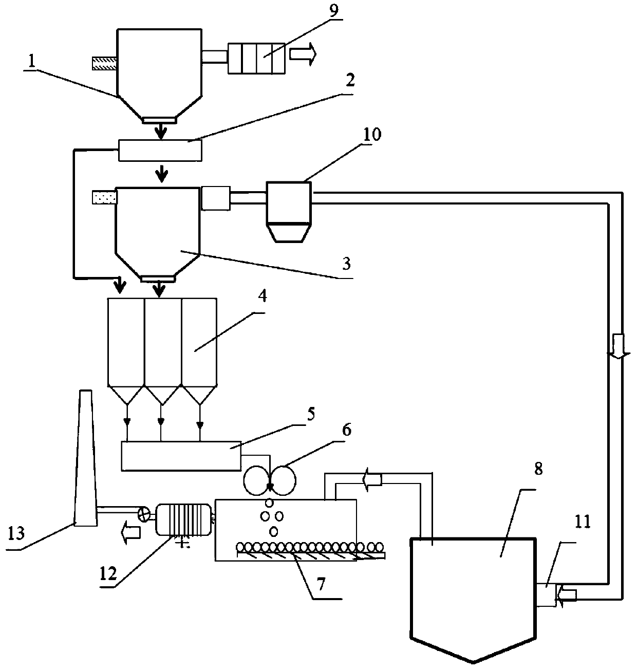
[0230] The process system and method for recovering waste heat from high-temperature particles using the above-mentioned device, the specific steps are as follows:

[0231] (1) Waste heat recovery in the high temperature section of copper slag particles

[0232] Copper slag particles (with a particle size range of 0.5-2 mm) and limestone (100 mesh) at 1100° C. enter the calciner 1 through the feeding device 7 . The temperature inside the calciner 1 is 600-1000°C, and the mass ratio o...


PUM

PropertyMeasurementUnit
Particle sizeaaaaaaaaaa

Abstract

The invention discloses a gradient waste heat recovery and direct reduction system and method for iron-containing metallurgical slag particles. The system comprises a waste heat recovery system, a material mixing system and a direct reduction system which are sequentially connected, wherein the waste heat recovery system comprises a calcining furnace, a separator and a pyrolyzing furnace; when a mode A is adopted, the calcining furnace, the separator and the pyrolyzing furnace are sequentially connected; and when a mode B is adopted, the calcining furnace, the pyrolyzing furnace and the separator are sequentially connected. The method comprises the following steps that the iron-containing metallurgical slag particles and a calcium carbonate precursor are calcined in proportion to obtain cooled particles and CaO, the CaO is separated or is added into carbon-containing solid waste together with the particles for pyrolysis to obtain solid semi-coke and cooled particles, the solid semi-coke and the cooled particles enter a stock bin together with the CaO, and after pelletizing is carried out according to needs, direct reduced iron is obtained through reduction. According to the systemand the method, the waste heat of the iron-containing metallurgical slag particles can be efficiently recovered, and the waste heat recovery efficiency, the efficiency and the iron recovery rate are greatly improved; and the particle waste heat is converted into the CaO and the solid semi-coke which are used as a slag forming agent and a reducing agent in the reduction process correspondingly, sothat in-situ consumption of materials is realized, and the system and the method have extremely high social value and economic value.

Description

Technical field: [0001] The invention belongs to the technical field of waste heat recovery and metallurgy energy saving, and in particular relates to a cascade waste heat recovery and direct reduction system and method of iron-containing metallurgical slag particles. Background technique: [0002] Metallurgical slag is a by-product discharged during the metal smelting process, such as blast furnace slag, steel slag, copper slag, nickel slag, lead slag, aluminum slag, etc. Metallurgical slag has the characteristics of high discharge temperature, complex composition, and high value of resource recovery and utilization. Taking blast furnace slag as an example, the temperature of blast furnace slag is about 1500°C, and the sensible heat per ton of slag is about 60kg of standard coal. my country's blast furnace slag output in 2018 can reach 250 million tons, equivalent to about 15 million tons of standard coal. Therefore, the realization of efficient and clean waste heat recov...

Claims


Application Information

Patent Timeline
IPC IPC(8): C21B13/00C21B3/08C22B1/248
CPCC21B13/0066C21B3/08C22B1/248C21B2400/022C21B2400/08Y02P10/143Y02P10/20
Inventor 左宗良张敬奎罗思义于庆波
Owner QINGDAO TECHNOLOGICAL UNIVERSITY
Why Eureka
Try Eureka