Thionyl chloride production system

A production system, technology of thionyl chloride, applied in the direction of thionyl chloride, sulfur and halogen compounds, etc., can solve the problems of increased floor space and investment, cumbersome process, increased system tail gas volume, etc., to reduce process complexity and , reduce process risk, and meet the effect of cooling demand

Inactive Publication Date: 2020-03-31
SHANDONG KAISHENG NEW MATERIALS
View PDF0 Cites 0 Cited by
  • Summary
  • Abstract
  • Description
  • Claims
  • Application Information

AI Technical Summary

Problems solved by technology

When the sulfur dioxide gas phase method is used for production, it has the advantages of cheap and easy-to-obtain process raw materials, high product quality and process yield, and low production cost. However, this method has the disadvantages of large equipment investment, cumbersome process, and high energy consumption.
[0004] In the process of producing thionyl chloride by sulfur dioxide gas phase process, the catalytic condenser in the catalytic reaction stage and the top condenser of each rectification tower in the product rectification stage are ordinary circulating water condensers. Once the condenser leaks, there will be a relatively large safety risk. Specifically It is due to the violent reaction between thionyl chloride and water to generate hydrogen chloride and sulfur dioxide, resulting in rapid expansion of local volume, which may cause an explosion. The continuous fouling of circulating water in the process of circulating in the condenser makes the heat transfer effect

Method used


Image

  • Thionyl chloride production system

Examples


Embodiment 1

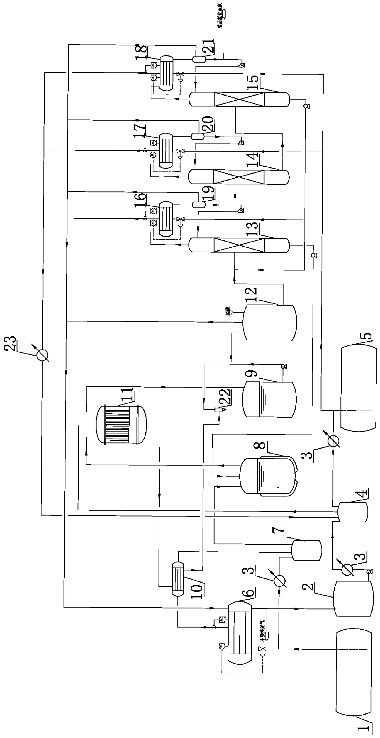
[0043] The thionyl chloride production system of the present invention comprises sulfur dioxide storage tank 5, weight removal tower 13, synthesis kettle 8, sulfur mixing kettle 12, catalytic reactor 11 and liquid chlorine storage tank 1, and liquid chlorine storage tank 1 passes through pipe The road is connected with the second buffer tank 7, and the second buffer tank 7 is connected with the synthesis kettle 8 through a pipeline; the bottom of the weight removal tower 13 is connected with the synthesis kettle 8 through a pipeline, and the synthesis kettle 8 is connected with the catalytic reactor 11 through a pipeline; Sulfur dioxide storage tank 5 links to each other with first buffer tank 4 by pipeline, and first buffer tank 4 links to each other with catalytic reactor 11 through pipeline; Catalytic reactor 11 bottom links to each other with catalytic condenser 10 through pipeline, catalytic condenser 10 bottom Link to each other with injector 22 through pipeline, injector...


PUM


Abstract

The invention belongs to the technical field of acyl chloride production devices, and particularly relates to a thionyl chloride production system. According to the thionyl chloride production system,a liquid chlorine storage tank is connected with the synthesis kettle through a pipeline; the bottom of a de-heavy tower is connected with a catalytic reactor through a pipeline; a sulfur dioxide storage tank is connected with a first buffer tank through a pipeline; the first buffer tank is connected with the catalytic reactor through a pipeline; the bottom of the catalytic reactor is connected with a catalytic condenser through a pipeline, the bottom of the catalytic condenser is connected with an ejector through a pipeline, and the ejector is connected with a crude product receiving kettle.According to the thionyl chloride production system, gasification latent heat of raw materials chlorine and sulfur dioxide is fully utilized; a part of raw materials chlorine and sulfur dioxide are used as cooling cold sources of the whole production system, construction of public engineering of a circulating water system and a refrigeration system is avoided, process complexity and system energyconsumption (including electricity, water and steam) are reduced, access of circulating water is avoided in the process, and process risks of the whole system are reduced.

Description

technical field [0001] The invention belongs to the technical field of acid chloride production devices, and in particular relates to a production system of thionyl chloride. Background technique [0002] Thionyl chloride is also known as thionyl chloride or sulfur oxychloride, with the molecular formula SOCl 2 , molecular weight 118.97, colorless or light yellow liquid under normal temperature and pressure, with pungent odor. The relative density is 1.676, the melting point is -104.5°C, and the boiling point is 78.8°C. When meeting with water, it is easily decomposed into sulfur dioxide and hydrogen chloride. Thionyl chloride is an important organic chemical intermediate, mainly used in pharmaceutical, pesticide and dye industries. [0003] The main production processes of thionyl chloride include chlorosulfonic acid method, co-production method, sulfur dioxide and sulfur trioxide gas phase method. When the sulfur dioxide gas phase method is used for production, it has ...

Claims


Application Information

Patent Timeline
IPC IPC(8): C01B17/45
CPCC01B17/4584
Inventor 张良谢圣斌张善民张泰铭刘嵩孙丰炜王廷肖广明
Owner SHANDONG KAISHENG NEW MATERIALS
Why Eureka
Try Eureka