Preparation method of Zr-Si-O amorphous protective coating for nuclear power

A protective coating, zr-si-o technology, applied in coatings, nuclear power generation, metal material coating technology, etc., can solve the problems of volume expansion, weak toughness and high hardness, etc., to improve service life, good resistance Oxidation property, effect of uniform coating composition

Inactive Publication Date: 2020-05-29
ZHENGZHOU UNIV
View PDF6 Cites 3 Cited by
  • Summary
  • Abstract
  • Description
  • Claims
  • Application Information

AI Technical Summary

Problems solved by technology

However, due to its weak toughness and high hardness, the oxide film usually contains small pores and wavy cracks, and at the same time, the oxide phase transformation brings obvious volume expansion and the resulting cracks

Method used


Image

  • Preparation method of Zr-Si-O amorphous protective coating for nuclear power
  • Preparation method of Zr-Si-O amorphous protective coating for nuclear power
  • Preparation method of Zr-Si-O amorphous protective coating for nuclear power

Examples


Embodiment 1

[0035] Choose Zr-4 and pure Si target as the sputtering target, use a single crystal silicon wafer as the coating substrate, conduct ultrasonic treatment with acetone, alcohol, and deionized water for 20 minutes, and then dry it with a high-purity nitrogen gun for later use; When the chamber vacuum reaches 5×10 -4 At around mbar, the Zr-4 layer is deposited first. Connect the Zr-4 target to a target site connected to a direct current (DC) power supply. Connect the Si target to a target site connected to a radio frequency (RF) power source. The air pressure in the chamber reaches 5×10 -4 When it is below Pa, open the process gas valve to feed Ar, set the gas flow rate of Ar to 20sccm through the gas flow meter, and adjust the air pressure in the vacuum chamber to 0.5 Pa (±0.01Pa) by adjusting the plug valve of the molecular pump ; Turn on the DC power supply, adjust the current of the DC power supply to 0.400A (±0.005A), the voltage to 190V (±2V), and start sputtering coati...

Embodiment 2

[0038] Choose Zr-4 and pure Si target as the sputtering target, use a single crystal silicon wafer as the coating substrate, conduct ultrasonic treatment with acetone, alcohol, and deionized water for 20 minutes, and then dry it with a high-purity nitrogen gun for later use; When the chamber vacuum reaches 5×10 -4 At around mbar, the Zr-4 layer is deposited first. Connect the Zr-4 target to a target site connected to a direct current (DC) power supply. Connect the Si target to a target site connected to a radio frequency (RF) power source. The air pressure in the chamber reaches 5×10 -4 When it is below Pa, open the process gas valve to feed Ar, set the gas flow rate of Ar to 20sccm through the gas flow meter, and adjust the air pressure in the vacuum chamber to 0.5 Pa (±0.01Pa) by adjusting the plug valve of the molecular pump ; Turn on the DC power supply, adjust the current of the DC power supply to 0.400A (±0.005A), the voltage to 190V (±2V), and start sputtering coati...

example 1

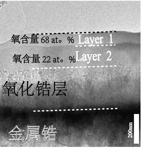
[0048] The result of the coating in Example 1 after a long-time air oxidation experiment is as follows: image 3 As shown, according to the EDS composition analysis, it can be seen that as the oxidation progresses, the amorphous Zr-Si-O thin film evolves into a stable double-layer structure, and the interface is well bonded. As the oxidation time increases, the thickness of the zirconium oxide layer below is limited, forming a typical parabolic form, and the layer2 layer tends to be stable, such as Figure 4 As shown, compared with the traditional zirconia passivation layer, it exhibits good oxidation resistance.


PUM

PropertyMeasurementUnit
thicknessaaaaaaaaaa
thicknessaaaaaaaaaa
diameteraaaaaaaaaa

Abstract

The invention provides a preparation method of a Zr-Si-O amorphous protective coating for nuclear power. The preparation method is characterized by comprising the following steps that (1), target material selection is carried out, a Zr-4 target material and a pure Si target material are selected as a sputtering target material, and a monocrystalline silicon wafer is selected as a coating substrate; and (2), coating preparation is carried out, the Zr-4 target material is connected to a target position connected with a direct-current power source, the Si target material is connected to a targetposition connected with a radio-frequency power source, a Zr-4 layer is deposited on the coating substrate firstly, the thickness of the Zr-4 layer is 800 nm, and then a Zr-Si-O thin film is depositedthrough a reaction co-sputtering method. According to the preparation method, a high-vacuum single-chamber three-target magnetron sputtering system is used for preparing the coating, the coating is uniform in component, compact in structure and good in film-substrate binding force, besides, the Zr-Si-O amorphous coating prepared through the method has excellent oxidation resistance and good corrosion resistance and can be applied to cladding materials of reactor elements and other fuel assembly structural components, and the service life is prolonged.

Description

technical field [0001] The invention relates to the field of ceramic coating protection, in particular to a preparation method of Zr-Si-O amorphous protective coating for nuclear power. Background technique [0002] Zr alloys are currently widely used as nuclear fuel cladding materials, but their oxidative corrosion behavior limits the life of fuel assemblies. The research and development of new fuel cladding takes a long time, and the cost is relatively high. From scientific experiments to mass production, there must be a systematic industrial chain support. The micro-addition and adjustment of alloying elements will cause great changes in the structure and properties. So far, the key factors affecting the corrosion resistance of zirconium alloys are still unclear. my country has introduced French M5 pipe technology, but in the end it has not produced M5 finished products. Coating technology is the most effective way in the short term. The introduction of coating technolo...

Claims


Application Information

Patent Timeline
Patent Type & Authority Applications(China)
IPC IPC(8): C23C14/08C23C14/16C23C14/35G21C3/07
CPCC23C14/0036C23C14/08C23C14/165C23C14/352G21C3/07Y02E30/30
Inventor 曹国钦胡俊华邵国胜仵康康
Owner ZHENGZHOU UNIV
Why Eureka
Try Eureka