Oil-water separation device and oil-water separation method

An oil-water separation device and technology for oil-water separation, which is applied in the field of oil-water separation devices and oil-water separation, can solve the problems of low removal rate, easy pollution, and low removal rate of oil droplets, and achieve the effect of high separation efficiency and simple structure

Active Publication Date: 2020-07-28
CHINA PETROLEUM & CHEM CORP +1
View PDF23 Cites 6 Cited by
  • Summary
  • Abstract
  • Description
  • Claims
  • Application Information

AI Technical Summary

Problems solved by technology

The on-line oil reduction technology for oily wastewater varies with the composition and state of the oily waste. Among them, the physical degreasing method is most widely used in the petrochemical industry, such as gravity separation, filtration, membrane separation, crude oil removal, etc. Granulation method and cyclone separation method, but with the further improvement of the production index of the device and the emulsified oil problem caused by the processing of inferior crude oil, the current physical deoiling method can no longer meet the requirements of the oil removal index or continuous operation cycl

Method used


Image

  • Oil-water separation device and oil-water separation method

Examples


Embodiment 1

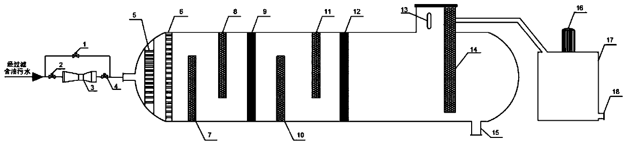
[0064] This embodiment provides an oil-water separation device, referring to figure 1 As shown, it includes a flow rate control unit, an oil-water separation unit and a dirty oil extraction and storage unit. The oil-water separation unit is set between the flow rate control unit and the waste oil extraction and storage unit. The filtered oily wastewater is first passed through the flow rate control unit to control the fluid flow rate, and then passed into the oil-water separation unit to separate oil and water. The separated oil Pass into the dirty oil and draw it out of the storage unit for storage.

[0065] The flow rate control unit includes a Venturi tube 3 , a second valve 2 and a third valve 4 are respectively arranged before and after the Venturi tube 3 , and a first valve 1 is also arranged on a pipeline connected in parallel with the Venturi tube 3 . When performing oil-water separation, the second valve 2 and the third valve 4 can be opened, and the oily waste water...

Embodiment 2

[0081] This embodiment provides an oil-water separation device, and the only difference from Embodiment 1 is that the first oil droplet polymerization separator 7, the second oil droplet polymerization separator 8, the third oil droplet polymerization separator 10 and the fourth oil droplet polymerization separator The materials of the drop polymerization separator 11 are all PVP, and in order to improve the hydrophilicity of the PVP, polyacrylic acid is sprayed on the surface of the PVP board.

[0082] The opening ratio of the oil droplet polymerization separator is 40%, and the inside is filled with polyurethane material. The polyurethane composite material is loaded with the first material and the second material. In this embodiment, the first material is nano-zinc oxide, and the second material is For ammonium polyphosphate, the diameter of the oil droplet polymerization separator is smaller than the diameter of the tank.

[0083] The rest of the structure and materials ar...

Embodiment 3

[0085] This embodiment provides an oil-water separation device, and the only difference from Embodiment 1 is that the first oil droplet polymerization separator 7, the second oil droplet polymerization separator 8, the third oil droplet polymerization separator 10 and the fourth oil droplet polymerization separator The materials of the drop polymerization separator 11 are all PVA, and no material is sprayed on the surface of the PVA plate in this embodiment.

[0086] The opening ratio of the oil droplet polymerization separator is 40%, and the inside is filled with a polyurethane material, and the polyurethane composite material is loaded with a first material and a second material. In this embodiment, the first material is nano-zinc oxide and graphene. The second material is polyhexammonium bromide, and the diameter of the oil drop polymerization separator is smaller than that of the tank body.

[0087] The rest of the structure and materials are the same as in Example 1.


PUM


Abstract

The invention provides an oil-water separation device and an oil-water separation method, belonging to an oil-water separation technology in the field of environmental protection. The oil-water separation device is simple in structure, high in separation efficiency and capable of operating for a long period. The oil-water separation device comprises an oil-water separation unit, wherein a liquid distributor, a liquid rectifier, an oil drop gathering partition plate, an oil-water layering strengthening partition plate and a dirty oil leading-out partition plate are arranged in the oil-water separation unit; and multiple structures in the oil-water separation unit are orderly arranged, so separation of oil and water in oily wastewater is facilitated. The oil-water separation device providedby the invention is high in oil-water separation efficiency, and can realize deep separation of oily wastewater.

Description

technical field [0001] The invention relates to oil-water separation technology in the field of environmental protection, in particular to an oil-water separation device and an oil-water separation method. Background technique [0002] With the increasingly stringent environmental protection standards, the requirements for the discharge indicators of oily wastewater in the petrochemical industry are also getting higher and higher. In recent years, with the heavy crude oil that can be processed, sewage treatment plants need to reduce the amount of oily wastewater generated at the end of different processes Chemical treatment to meet the biochemical water entry conditions. The on-line oil reduction technology for oily wastewater varies with the composition and state of the oily waste. Among them, the physical degreasing method is most widely used in the petrochemical industry, such as gravity separation, filtration, membrane separation, crude oil removal, etc. Granulation met...

Claims


Application Information

Patent Timeline
IPC IPC(8): B01D17/022B01D17/04B01D17/032
CPCB01D17/045B01D17/0214B01D17/0202
Inventor 杜延年裴旭东陈卫红李朝恒
Owner CHINA PETROLEUM & CHEM CORP
Why Eureka
Try Eureka