
Novel processing method for powder metallurgy brake pad friction block

A technology of powder metallurgy and processing method, which is applied in the direction of metal processing equipment, friction linings, mechanical equipment, etc., can solve the problems of separation and peeling of friction body and steel back, affect the safety of high-speed trains, and long preparation process, so as to achieve favorable The effect of convergence, reducing the number of labor used, and reducing production costs

Inactive Publication Date: 2020-08-28
漯河久铖智能装备有限公司
View PDF6 Cites 1 Cited by
  • Summary
  • Abstract
  • Description
  • Claims
  • Application Information

AI Technical Summary

Problems solved by technology

[0003] In the existing technology, the most widely used brake pads are powder metallurgy floating brake pads, which are mainly composed of friction blocks, support pads, back plates and spring clips, among which the friction blocks can be Partial floating, so as to obtain the maximum effective contact area of ​​the contact friction with the brake disc and a more stable and uniform braking pressure. However, during the braking process, because the friction block is frequently impacted by friction and thermal load, it is easy to produce The material fracture of the powder metallurgy friction body and the separation and peeling between the friction body and the steel back affect the safety of high-speed trains
[0004] The existing preparation method is to use a bell furnace for sintering. The preparation process is: compounding, mixing, pressing, pressureless sintering, assembling with rubberized friction plates, curing, and processing oil tanks. The preparation process is long and cumbersome. , using bell furnace for sintering, long production cycle and low production efficiency

Method used


Image

  • Novel processing method for powder metallurgy brake pad friction block
  • Novel processing method for powder metallurgy brake pad friction block

Examples


Embodiment Construction

[0037] The following will clearly and completely describe the technical solutions in the embodiments of the present invention with reference to the accompanying drawings in the embodiments of the present invention. Obviously, the described embodiments are only some, not all, embodiments of the present invention. Based on the embodiments of the present invention, all other embodiments obtained by persons of ordinary skill in the art without making creative efforts belong to the protection scope of the present invention.

[0038] see Figure 1-2 , in an embodiment of the present invention, a novel powder metallurgy brake pad friction block processing method includes the following steps:

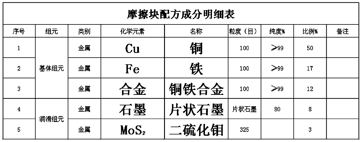
[0039] Step 1: Put iron-copper alloy particles, copper particles, and iron particles into the batching bucket. The particle size of iron-copper alloy particles, copper particles and iron particles is 100, and the ratio of iron-copper alloy is 12%, and the ratio of copper is 50%, the proportion...


PUM


Abstract

The invention discloses a novel processing method for a powder metallurgy brake pad friction block. The novel processing method comprises the following steps: proportioning, mixing, compacting, splicing and vacuum sintering. Through repeated test, performance of the friction block is improved by 50% or more and production efficiency is improved by 6.8 times or more on the original basis; vacuum pressure sintering is adopted, compacting can be performed in a compacting machine like a common powder metallurgy part, so that the production period is remarkably shortened, and production cost is reduced; a friction layer of a friction plate obtained by a vacuum pressure sintering process has lower porosity, so that a friction coefficient is higher; the most outstanding point is that relatively high shear strength can be kept as the friction plate is subjected to vacuum high-temperature sintering along with the friction block; and meanwhile, dimension precision also can be guaranteed by precision of a graphene mould in a vacuum pressure sintering furnace. The novel processing method reduces processes in production, reduces bad links in a production process, reduces number of used workers,and further reduces production cost.

Description

technical field [0001] The invention relates to the technical field of production of metallurgical brake pad friction blocks, in particular to a novel powder metallurgy brake pad friction block processing method. Background technique [0002] High-speed trains refer to railway trains whose maximum speed reaches or exceeds 200km / h. With the rapid development of my country's high-speed railway and high-speed train technology, the performance requirements of the braking system are constantly improving. Brake pads are the key components of the basic braking system of high-speed trains, which directly affect the safety of train operation. Brake pads need to be high-speed The huge kinetic energy generated when the train brakes is converted into heat energy, so the brake pads are required to have high mechanical strength, good heat resistance and fatigue resistance. [0003] In the existing technology, the most widely used brake pads are powder metallurgy floating brake pads, which...

Claims


Application Information

Patent Timeline
IPC IPC(8): B22F1/00B22F3/02B22F3/14F16D69/02C22C9/00C22C32/00C22C1/05C22C1/10
CPCB22F3/02B22F3/14F16D69/027B22F3/1216C22C9/00C22C32/0084C22C1/05F16D2200/0026F16D2200/0073F16D2200/0065B22F1/105
Inventor 司云川
Owner 漯河久铖智能装备有限公司
Learn More