Photo-thermal micropump based on capillary optical fiber
A technology of capillary tube and micropump, which is applied to components, pumps, and optics of pumping devices for elastic fluids, and can solve problems such as complex manufacturing processes, difficult integration, and increased system complexity
- Summary
- Abstract
- Description
- Claims
- Application Information
AI Technical Summary
Problems solved by technology
Method used
Image

Examples
Embodiment Construction
[0051] The present invention will be further described below in conjunction with the accompanying drawings and specific embodiments.
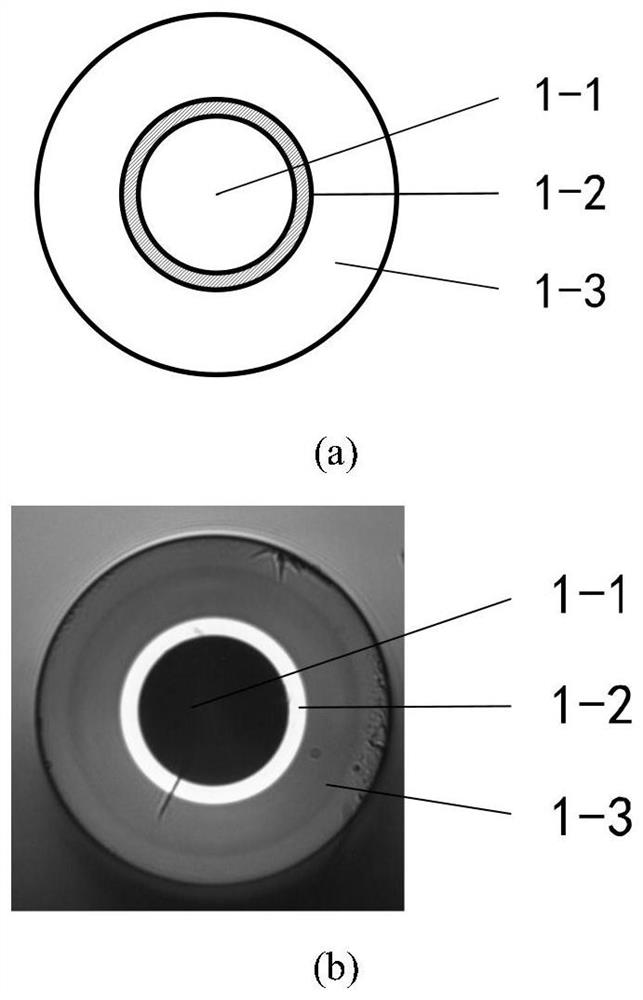
[0052] figure 1 Shown is a cross-sectional view of a capillary fiber consisting of a thin layer, an annular core with a refractive index slightly higher than that of the cladding material, and an air hole structure that allows access to microfluidics.
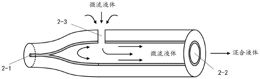
[0053] figure 2 It shows that one end of the capillary optical fiber is heated and fused, so that the capillary pores are collapsed and closed to form a solid light wave channel 2-1, thereby becoming an optical interface connected with an external energy source, and the other unprocessed end is an open channel Port 2-2, which is both the outlet of the micropump and the inlet of the chip microfluidics. The side femtosecond hole punching technology is used on the outer surface of the optical fiber near the shrinkage end to process and manufacture a microfluidic material micropore channel entran...
PUM
 Abstract
Description
Claims
Application Information
 - R&D
- Intellectual Property
- Life Sciences
- Materials
- Tech Scout
- Unparalleled Data Quality
- Higher Quality Content
- 60% Fewer Hallucinations
Browse by: Latest US Patents, China's latest patents, Technical Efficacy Thesaurus, Application Domain, Technology Topic, Popular Technical Reports.
© 2025 PatSnap. All rights reserved.Legal|Privacy policy|Modern Slavery Act Transparency Statement|Sitemap|About US| Contact US: help@patsnap.com