Ultrathin micro-heat pipe with micro-channel capillary structure and preparation method thereof

A technology of capillary structure and microchannel, which is applied in the direction of microstructure technology, microstructure device, manufacturing microstructure device, etc., can solve problems such as difficult to use directly, and achieve the effect of avoiding small cavity diameter and improving heat dissipation performance

Active Publication Date: 2020-09-08
CHANGZHOU UNIV +2
View PDF5 Cites 2 Cited by
  • Summary
  • Abstract
  • Description
  • Claims
  • Application Information

AI Technical Summary

Problems solved by technology

Excellent thermal conductivity, toughness, and fracture strength make it a great potential for development in the field of thermal management, but these properties are based on the microscopic nanoscale, which is difficult to use directly

Method used


Image

  • Ultrathin micro-heat pipe with micro-channel capillary structure and preparation method thereof
  • Ultrathin micro-heat pipe with micro-channel capillary structure and preparation method thereof
  • Ultrathin micro-heat pipe with micro-channel capillary structure and preparation method thereof

Examples


preparation example Construction

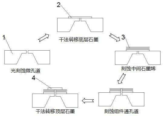
[0031] The preparation method steps are as follows:

[0032] Step a: using standard photolithography and reactive ion etching to etch a micron-scale rectangular channel in the middle of the silicon nitride wafer of the silicon nitride substrate 1 with a thickness of 90-120 μm;

[0033] Step b: Cover the channel obtained in step a with a layer of graphite with a thickness of 8-15 nm by dry transfer, which is marked as bottom graphite 2;

[0034] Step c: covering the bottom graphite 2 with graphene containing different layers and etched into equidistant strips by electron beam lithography and oxygen plasma, marking it as the middle layer graphene 3, and then covering it with dry transfer method The bottom graphite 2 surface and the long sides of the graphene are arranged vertically with the microchannels;

[0035] Step d: using the oxygen reactive ion etching process in step a to etch away the overlapped part of the bottom layer graphite 2 and the middle layer graphene 3 with t...

Embodiment 1

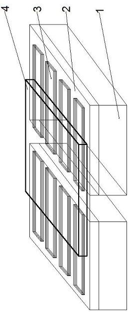
[0045] to combine figure 1 , the micro heat pipe capillary structure of the present invention comprises a silicon nitride substrate 1, a bottom graphite 2 arranged on a silicon nitride substrate 1, an intermediate layer of graphene 3 and a top layer of graphite 4, wherein the silicon nitride substrate 1 , the bottom layer of graphite 2 and the middle layer of graphene 3 have a microchannel structure with a width of 3 μm.

[0046] The preparation process of the micro heat pipe microchannel capillary structure of the present invention is as follows:

[0047] (1) Clean the silicon nitride wafer with a thickness of 100 μm in sequence with acetone, ethanol and deionized water, blow it dry with nitrogen and put it in an oven for 5 minutes; spin-coat photoresist on the surface of the silicon nitride wafer and put it in an oven at 100°C for drying Bake for 10 minutes; place a mask plate with 3×20 μm rectangular micro-holes on the silicon nitride wafer coated with photoresist, after c...

Embodiment 2

[0054] to combine figure 1 , the micro heat pipe capillary structure of the present invention comprises a silicon nitride substrate 1, a bottom graphite 2 arranged on a silicon nitride substrate 1, an intermediate layer of graphene 3 and a top layer of graphite 4, wherein the silicon nitride substrate 1 , the bottom layer of graphite 2 and the middle layer of graphene 3 have a microchannel structure with a width of 5 μm.

[0055] The preparation process of the micro heat pipe microchannel capillary structure of the present invention is as follows:

[0056] (1) Clean the silicon nitride wafer with a thickness of 100 μm in sequence with acetone, ethanol and deionized water, blow it dry with nitrogen and put it in an oven for 5 minutes; spin-coat photoresist on the surface of the silicon nitride wafer and put it in an oven at 100°C for drying Bake for 10 minutes; place a mask plate with 4×20 μm rectangular microholes on the silicon nitride wafer coated with photoresist, after ca...


PUM

PropertyMeasurementUnit
thicknessaaaaaaaaaa

Abstract

The invention relates to the technical field of heat dissipation equipment, in particular to an ultrathin micro-heat pipe with a micro-channel capillary structure. The ultrathin micro-heat pipe comprises a silicon nitride substrate, bottom-layer graphite, middle-layer graphene and top-layer graphite which are sequentially arranged from bottom to top, wherein the middle-layer graphene is long-strip-shaped and is arranged at equal intervals, micron-sized rectangular channels are formed in the silicon nitride substrate, the bottom-layer graphite and the middle-layer graphene, specifically, the rectangular channels are rectangles with a section width of 3-5 microns and a height of 18-22 microns, and the interval between the middle-layer graphene is 120-130nm. The micro-channel structure formedby the invention is micron-scale or nano-scale, and has high capillary pressure and large sliding length, so that the flow velocity of a working medium liquid in the heat pipe is obviously increased,and the liquid in a condensation section in the heat pipe can quickly flow back to the evaporation section.

Description

technical field [0001] The invention relates to the technical field of heat dissipation equipment, in particular to an ultra-thin micro heat pipe with a microchannel capillary structure and a preparation method thereof. Background technique [0002] With the development of electronic information technology, chip heat dissipation technology is facing the problem of miniaturization and integration. The heat flux of electronic chips per unit time has been greatly increased, resulting in a sharp decrease in heat dissipation efficiency in a small space. The birth of micro heat pipe technology can solve the problems of small space, low heat dissipation efficiency, slow thermal response and low stability to a certain extent. [0003] However, the heat transfer performance of micro heat pipes in existing electronic products is mainly affected by the capillary structure of the inner wall of the tube. The high capillary adsorption force, small return flow resistance and high heat tra...

Claims


Application Information

Patent Timeline
Patent Type & Authority Applications(China)
IPC IPC(8): H01L23/427B81B1/00B81C1/00B82Y40/00
CPCH01L23/427B81B1/004B81C1/00087B82Y40/00
Inventor 弓晓晶许敬储富强郭国标
Owner CHANGZHOU UNIV
Why Eureka
Try Eureka