Continuous treatment method for organic waste gas based on circulating fluidized bed system

A circulating fluidized bed and organic waste gas technology, applied in chemical instruments and methods, combustion methods, separation methods, etc., can solve problems such as accumulation of fire, inconvenient operation, and increased energy consumption

Active Publication Date: 2020-09-29
JIANGSU NANFANG COATING & ENVIRONMENT PROTECTION EQUIP +1
View PDF15 Cites 0 Cited by
  • Summary
  • Abstract
  • Description
  • Claims
  • Application Information

AI Technical Summary

Problems solved by technology

However, the activated carbon tower in this process needs to be cyclically switched between adsorption and desorption, which is inconvenient to operate, and there is a potential risk of local overheating and ignition of activated carbon
Utility model patent CN208694621U discloses a zeolite runner-catalytic combustion system for treating organic waste gas. The regeneration gas preheating unit is equipped with furnace gas mixing and direct heating after combustion waste heat exchange, which improves the utilization rate of combustion heat energy, but the In the system, the adsorption area and the desorption area are the same part, and there is still the problem of alternating heating and cooling of the equipment, and there are moving parts
However, additional heating pipes are arranged

Method used


Image

  • Continuous treatment method for organic waste gas based on circulating fluidized bed system
  • Continuous treatment method for organic waste gas based on circulating fluidized bed system
  • Continuous treatment method for organic waste gas based on circulating fluidized bed system

Examples


Embodiment 1

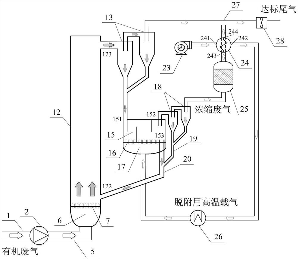
[0083] Such as figure 1 The structure of circulating fluidized bed system 1 adopted by the continuous treatment method of organic waste gas based on circulating fluidized bed system is shown. The system includes: organic waste gas main pipe 1, fluidization fan 2, riser intake pipe 5, lifting Pipe bottom fluidization air chamber 6, riser air distribution plate 7, riser 12, riser separator 13, desorption chamber 15, desorption chamber air distribution plate 16, desorption carrier gas air chamber 17, desorption chamber separator 18. Material leg 19, desorption chamber discharge pipe 20, regeneration fan 23, heat exchanger 24, VOCs gas incinerator 25, electric heater 26, tail gas flue 27, induced draft fan 28. The air outlet of the organic waste gas main pipe 1 is provided with a fluidization fan 2, and the air outlet of the fluidization fan 2 is connected to the air inlet of the fluidization air chamber 6 at the bottom of the riser through the riser inlet main pipe 5, and the lif...

Embodiment 2

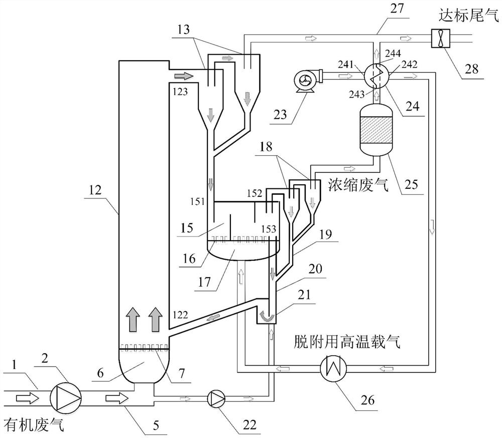
[0102] Such as figure 2 As shown, further, based on the above system one, the present invention also provides an improved circulating fluidized bed system two capable of realizing continuous treatment of organic waste gas. In addition to the components in system one, system two also adds a return device, also known as a particle circulation control device, whose function is not only to adjust and control the particle circulation to achieve the required particle circulation rate; 12 to the desorption chamber 15, especially for this system where the reaction process and gas composition in the riser 12 and the desorption chamber 15 are different, it is particularly important to prevent the gas from "counter-channeling". The material return device includes a material return valve 21, a material return air booster fan 22 and corresponding connecting air ducts. The material return device includes a material return valve 21, a material return air booster fan 22 and corresponding co...

Embodiment 3

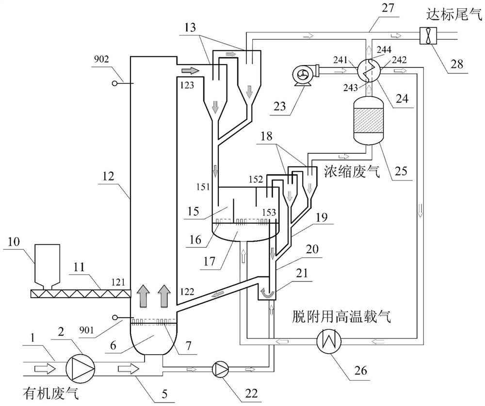
[0106] Such as image 3 As shown, further, based on the above system two, the present invention also provides an improved circulating fluidized bed system three capable of realizing continuous treatment of organic waste gas. In addition to the components in system two, system three also includes a feeding device, which includes a silo 10 for holding adsorbent particles, a high-pressure screw feeder 11, and the high-pressure screw feeder 11 is arranged on the adsorption The front wall feeding port 121 of the riser 12 of the device and the high-pressure screw feeder 11 are arranged below the feed bin 10; the catalyst particles in the riser 12 are passed through the high-pressure screw feeder 11 from the riser 12 The feed port 121 of the front wall is fed into. In addition, an upper pressure measuring point 902 and a lower pressure measuring point 901 are arranged on the riser 12, the lower pressure measuring point 901 is arranged on the upper side of the riser air distribution ...


PUM


Abstract

The invention discloses a continuous treatment method for organic waste gas based on a circulating fluidized bed system, belonging to the field of environmental protection. The method comprises the following steps that: adsorbent particles in a riser are fluidized by using organic waste gas to be treated and adsorb VOCs gas components in the organic waste gas; after purified tail gas flow carryinga part of the adsorbent particles is subjected to gas-solid separation, the adsorbent particles fall into a desorption chamber; high-temperature carrier gas for desorption enables the adsorbent particles in the desorption chamber to be fluidized and enables the VOCs gas components attached to the adsorbent particles to be desorbed, so the adsorbent particles are regenerated and returned to the riser; and concentrated waste gas carrying a part of the adsorbent particles and containing high-concentration VOCs gas is subjected to gas-solid separation, then enters an incineration device to be incinerated, oxidized and degraded into harmless high-temperature tail gas, and a heat recovery device recovers heat in the high-temperature tail gas and then converges the heat into a tail gas flue. According to the method, the adsorbent particles are in a fluidized state, adsorption and desorption efficiency is high, and a heat utilization rate is high.

Description

technical field [0001] The invention relates to the field of organic waste gas treatment, in particular to a continuous treatment method for organic waste gas based on a circulating fluidized bed system. Background technique [0002] Volatile Organic Compounds (Volatile Organic Compounds, VOCs) include non-methane hydrocarbons, oxygen-containing organic compounds, chlorine-containing organic compounds, nitrogen-containing organic compounds, and sulfur-containing organic compounds. harm. VOCs come from a wide range of sources and are produced during production, transportation or storage in petrochemical, transportation, printing, coating, pharmaceutical, furniture and other industries. my country's environmental protection department has also put forward increasingly stringent requirements for VOCs governance in various industries. [0003] There are many VOCs treatment technologies, including adsorption method, absorption method, thermal oxidation method, biodegradation me...

Claims


Application Information

Patent Timeline
IPC IPC(8): B01D53/12F23G7/06
CPCB01D53/12Y02A50/20
Inventor 李爱军柯希玮
Owner JIANGSU NANFANG COATING & ENVIRONMENT PROTECTION EQUIP
Why Eureka
Try Eureka