Eureka AIR delivers breakthrough ideas for toughest innovation challenges, trusted by R&D personnel around the world.

Civil engineering building waste treatment device

A construction waste and processing device technology, applied in cleaning devices, grain processing, transportation and packaging, etc., can solve problems affecting work efficiency, poor use of construction waste, decentralized functions, etc., and achieve the effect of improving work efficiency

Pending Publication Date: 2020-09-29
江苏航运职业技术学院
View PDF11 Cites 7 Cited by
  • Summary
  • Abstract
  • Description
  • Claims
  • Application Information

AI Technical Summary

Problems solved by technology

[0004] However, the civil engineering and construction waste treatment devices in the prior art generally use electromagnets and conveyor belts inside the device to absorb and remove iron impurities mixed in the crushed construction waste. The iron impurities adsorbed on the surface are cleaned up, which seriously affects the work efficiency; secondly, the civil engineering construction waste treatment device in the prior art does not have the function of dispersing the pulverized construction waste put into the device, resulting in the crushed construction waste The iron impurities mixed in the ground are not completely removed, so that the quality of the processed construction waste is poor, resulting in a poor basis for the subsequent reuse of the processed construction waste; in addition, the civil engineering construction waste treatment device in the prior art During the process of inputting crushed construction waste into the device from the feeding port, the input crushed construction waste tends to fall to the bottom of the conveyor belt, which often causes the input crushed construction waste to be mixed with the separated iron impurities again and needs to be re-mixed The pulverized construction waste is subjected to iron removal operation again, thereby increasing the labor load of the staff; in addition, during the work of the civil engineering construction waste processing device in the prior art, the surface of the conveyor belt is easy to adhere to iron impurities, resulting in The iron debris adhering to the conveyor belt surface is mixed again with the input crushed construction waste

Method used


Image

  • Civil engineering building waste treatment device
  • Civil engineering building waste treatment device
  • Civil engineering building waste treatment device

Examples


Embodiment 1

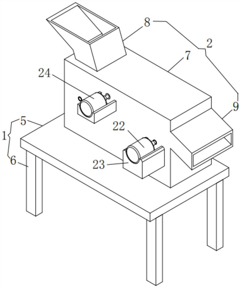
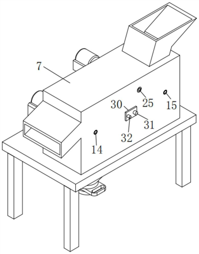
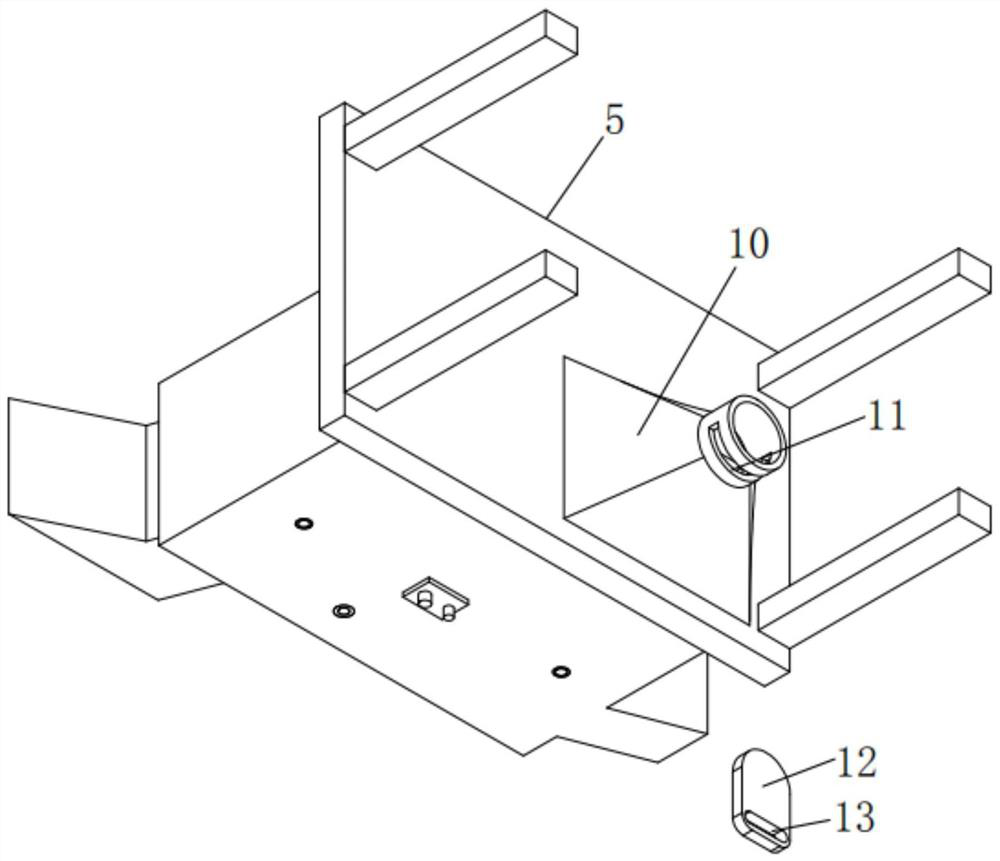
[0043] A civil engineering construction waste treatment device, such as figure 1 , 4 As shown in and 5, it includes a support unit 1, a frame 2, an iron removal unit 3 and a dispersion unit 4, the frame 2 is fixedly installed on the top of the support unit 1, and the iron removal unit 3 is fixedly installed on the On the frame 2, the dispersing unit 4 is fixedly installed on the frame 2, and the dispersing unit 4 is located above the iron removing unit 3.

[0044] By adopting the above technical scheme, the support unit 1 is used as the installation base of the device, the frame 2 is used to install the iron removal unit 3 and the dispersion unit 4, and the iron removal unit 3 is used for crushing the construction waste thrown into the frame 2 The mixed iron impurities are removed, and the dispersing unit 4 is used to air-disperse the crushed construction waste put into the frame 2, so that the iron impurities mixed in the crushed construction waste can fully contact the uppe...

Embodiment 2

[0065] The difference from Example 1 is that a protective layer is also provided on the inner surface of the square housing 7, and the protective layer is prepared by the following method:

[0066] Take the following raw materials and weigh them by weight: 13-18 parts of epoxy resin, 8-10 parts of calcium carbonate powder, 12-16 parts of polytetrafluoroethylene, 11-13 parts of aluminum oxide powder, and 5-8 parts of graphite powder , 10-13 parts of phenolic resin, 2-4 parts of alcohol ester dodecane, 2-4 parts of triethanolamine, 1-3 parts of polydimethylsiloxane and 30-50 parts of water;

[0067] S1. Add the weighed alcohol ester dodecane, triethanolamine, polydimethylsiloxane and water into the mixer and stir for 18-25min at a stirring speed of 700-900r / min to prepare a mixed solution;

[0068] S2, adding epoxy resin, calcium carbonate powder, polytetrafluoroethylene, aluminum oxide powder, graphite powder and phenolic resin into the pulverizer and pulverizing until the part...


PUM


Abstract

The invention relates to the technical field of building waste treatment, in particular to a civil engineering building waste treatment device. The civil engineering building waste treatment device comprises a supporting unit, a rack, an iron removing unit and a dispersion unit. The rack is fixedly mounted on the upper portion of the supporting unit, and the iron removing unit is fixedly mounted on the rack. According to the civil engineering building waste treatment device, when removed iron impurities are cleaned away, non-halt work can be achieved, the working efficiency is greatly improved, the iron impurities mixed in smashed building waste are completely removed, the quality of the treated building waste is good, a good use foundation is laid for following reutilization of the treated building waste, the situation that the input smashed building waste is mixed with the separated iron impurities again can be effectively avoided, thus, the labor amount of workers is effectively reduced, the iron impurities attached to the surface of a conveying belt can be scraped and fall into a collecting hopper, and the iron impurities attached to the surface of the conveying belt can be effectively prevented from being mixed with the input smashed building waste again.

Description

technical field [0001] The invention relates to the technical field of construction waste treatment, more specifically, it relates to a civil engineering construction waste treatment device. Background technique [0002] Construction waste refers to the dregs, spoils, waste materials, silt and other wastes generated during the construction, laying or demolition, and repair of various buildings, structures, and pipe networks by construction units or individuals. [0003] With the development of the construction industry, the renewal of buildings is changing with each passing day, resulting in a large amount of construction waste. If the construction waste is discarded without treatment, it will not only cause waste of resources, but also cause serious environmental pollution. Therefore, the construction waste is treated and reused. It is very necessary. In the process of processing construction waste, it is necessary to first crush the construction waste, and then remove the ...

Claims


Application Information

Patent Timeline
Patent Type & Authority Applications(China)
IPC IPC(8): B02C13/06B02C13/28B02C13/286B02C13/30B03C1/22B03C1/30B65G45/12C09D163/00C09D127/18C09D161/06C09D7/61C09D7/63C09D7/65
CPCB02C13/06B02C13/2804B02C13/286B02C13/30B02C2013/28609B02C2013/28618B03C1/22B03C1/30B65G45/12C08K2003/2227C08K2003/265C08L2205/035C09D127/18C09D161/06C09D163/00C09D7/61C09D7/63C09D7/65C08L27/18C08L61/06C08K13/02C08K3/26C08K3/04C08K3/22C08L63/00
Inventor 戴雨陈皓文王浩丞房世龙史誉州
Owner 江苏航运职业技术学院
Why Eureka
Eureka Blog
Learn More