Landfill leachate treatment system

A landfill leachate and treatment system technology, applied in the field of landfill leachate treatment systems, can solve the problems of impact on normal operation of sewage treatment plants and high investment costs

Pending Publication Date: 2020-10-20
中科建环有限责任公司
View PDF0 Cites 0 Cited by
  • Summary
  • Abstract
  • Description
  • Claims
  • Application Information

AI Technical Summary

Problems solved by technology

[0006] The purpose of the invention is to provide a landfill leachate treatment system to solve the technical problems in the prior art that the landfill leachate

Method used


Image

  • Landfill leachate treatment system

Examples


Embodiment 1

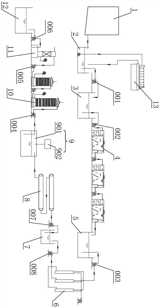
[0026] see figure 1 , the landfill leachate treatment system of this embodiment includes a garbage storage area 1, a liquid collection tank 2, a first sedimentation tank 3, an air flotation machine 4, a second sedimentation tank 5, a filter device, an ammonia nitrogen stripping tower 10 and a dewatering tank. Gas tower 11 and clean water pool 12.

[0027] The bottom liquid collection pipe of the garbage storage area 1 is connected to the liquid collection pool 2, the garbage storage area 1 is used to store garbage, and the leachate produced by the garbage flows into the liquid collection pool 2 after being collected by the liquid collection pipe at the bottom. Generally, the liquid collection pool 2 is usually greater than 100m 3 . The supernatant of the liquid collection tank 2 is sucked into the first sedimentation tank 3 by the first suction pump 001, and the first sedimentation tank 3 can be used for the precipitation of garbage permeate, and the heavy impurities are dep...

Embodiment 2

[0035] On the basis of embodiment one, the filter device of the present embodiment comprises SMBR ultrafiltration membrane 6 and RO reverse osmosis membrane 8, and the water inlet end of described SMBR ultrafiltration membrane 6 is connected with described second sedimentation tank 5, and water outlet The end is connected to the water inlet end of the RO reverse osmosis membrane 8, and the water outlet end of the RO reverse osmosis membrane 8 is connected to the ammonia nitrogen stripping tower 10.

[0036] Among them, the SMBR ultrafiltration membrane only allows water molecules, beneficial minerals and trace elements in the water to pass through, bacteria and colloids, rust, suspended solids, sediment, macromolecular organic matter, etc. The ultrafiltration membrane is intercepted, thereby realizing the purification process of the water body; water molecules can pass through the RO reverse osmosis membrane, while impurities such as inorganic salts, heavy metal ions, organic m...

Embodiment 3

[0040] On the basis of embodiment two, the third sedimentation tank 7 is also provided between the SMBR ultrafiltration membrane 6 and the RO reverse osmosis membrane 8 of the present embodiment, and the drain end of the SMBR ultrafiltration membrane 6 is connected to the first Three sedimentation tanks 7, the sedimentation tank is used to store the water treated by the SMBR ultrafiltration membrane, the water inlet end of the RO reverse osmosis membrane 8 is connected to the third sedimentation tank 7 through the seventh suction pump 007 Below the liquid level, the reverse osmosis membrane takes water in the third sedimentation tank, and the design of the third sedimentation tank can provide a buffer between the SMBR ultrafiltration membrane and RO reverse osmosis membrane to solve the SMBR The ultrafiltration membrane and the RO reverse osmosis membrane have different processing speeds.

[0041] Preferably, the drain pipe of the SMBR ultrafiltration membrane 6 is also provid...


PUM


Abstract

The invention relates to a landfill leachate treatment system. The system comprises a garbage storage area, a liquid collection tank, a first sedimentation tank, an air flotation machine, a second sedimentation tank, a filtering device, an ammonia nitrogen stripping tower, a degassing tower and a clean water tank which are arranged in sequence. According to the invention, suspended impurities in landfill leachate are removed by utilizing the air flotation machine; fine impurities in a water body are removed through the filtering device; ammonia gas in the water body is removed through the ammonia nitrogen stripping tower; and finally, carbon dioxide in the water body is removed through the degassing tower, so purified water with good water quality is finally obtained. The whole treatment system is low in investment cost, small in occupied area, good in effluent quality and suitable for large-scale application and popularization.

Description

technical field [0001] The invention relates to the technical field of landfill leachate treatment, in particular to a landfill leachate treatment system. Background technique [0002] With the increase of my country's urban population, the expansion of city scale and the improvement of residents' living standards, the output of urban domestic waste in my country is increasing sharply. Landfill leachate is a kind of high-concentration organic wastewater that is difficult to treat. It mainly comes from the following three aspects: 1. Natural rainfall and runoff in the landfill; 2. Water contained in the garbage itself; 3. After the landfill Water produced as a result of anaerobic decomposition by microorganisms. The precipitation in the landfill is the main part. [0003] Landfill leachate has the characteristics of complex water quality, heavy metal content, and poor biodegradability. In the prior art, the landfill leachate is usually discharged to the urban sewage plant ...

Claims


Application Information

Patent Timeline
IPC IPC(8): C02F9/02C02F9/04C02F103/06
CPCC02F1/001C02F1/20C02F1/24C02F1/441C02F1/444C02F1/58C02F9/00C02F2001/007C02F2103/06
Inventor 韩善国韩震
Owner 中科建环有限责任公司
Why Eureka
Try Eureka