Preparation method of hydrogenation and residual carbon removal catalyst

A technology for removing carbon residues and catalysts, which is applied in the field of preparation of hydrogenation carbon residue removal catalysts. It can solve the problems of unfavorable diffusion of macromolecular reactants, increased surface acid content, and high pore content, and achieves suitable acid strength distribution and pore structure. Moderate, high acid effect

Active Publication Date: 2020-10-27
CHINA PETROLEUM & CHEM CORP +1
View PDF6 Cites 1 Cited by
  • Summary
  • Abstract
  • Description
  • Claims
  • Application Information

AI Technical Summary

Problems solved by technology

The catalyst prepared by this method has a relatively high 6-8nm pore content and a relatively small macropore content, which is not co

Method used


Image

  • Preparation method of hydrogenation and residual carbon removal catalyst
  • Preparation method of hydrogenation and residual carbon removal catalyst
  • Preparation method of hydrogenation and residual carbon removal catalyst

Examples


preparation example Construction

[0028] Preparation of Material B:

[0029] (1) Preparation of material B1

[0030] 200 grams of kaolin was placed in a high-temperature muffle furnace and activated at 850° C. for 5 hours. Weigh 100 grams of the above-mentioned activated kaolin, 400 grams of ammonium bicarbonate, add 1500 grams of distilled water to the above materials and stir for 20 minutes, transfer the mixed materials into an autoclave and seal it and heat it up to 80 degrees Celsius at a speed of 10 degrees Celsius / min The temperature was kept constant for 3 hours, then the temperature was raised to 135°C at a rate of 5°C / min for 5 hours, and then the material was dried at 110°C for 6 hours and calcined at 750°C for 5 hours.

[0031] Weigh 50 grams of the above-mentioned materials, place them in a beaker, add 1500 grams of hydrochloric acid solution with a mass percentage concentration of 25% into the beaker, place the beaker in an ultrasonic container for ultrasonic treatment, the ultrasonic frequency i...

Embodiment 1

[0037] (1) Mix 5 grams of starch and 200 grams of pseudo-boehmite evenly to prepare mixed material A.

[0038] (2) Put 100g of mixed material A in the turntable molding machine and mix thoroughly, adjust the inclination angle of the turntable to 40º, and the rotation speed of the turntable to 10rpm; spray the acetic acid aqueous solution with a mass concentration of 2% on the mixed material A in the turntable through the sprayer After mixing and contacting, the molding time of the material in the turntable is 30 minutes, and the precursor I with a diameter of 1.0-1.5 mm is obtained;

[0039] (3) Put 100g of material B1 and the precursor I prepared in step (2) into the turntable molding machine and mix thoroughly, adjust the inclination angle of the turntable to 40º, and the rotation speed of the turntable to 10rpm, spray the acetic acid aqueous solution with a mass concentration of 2% After being sprayed on the materials in the turntable and mixed and contacted, the molding ti...

Embodiment 2

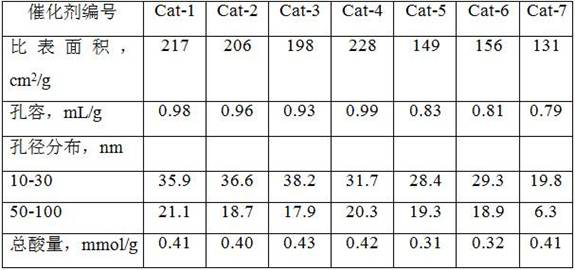
[0042] The same as in Example 1, except that the amount of starch added in the mixed material A is 8 grams, and the material B1 is replaced with material B3 to obtain the hydrogenation carbon removal catalyst Cat-2, and the properties of the catalyst are shown in Table 1.


PUM

PropertyMeasurementUnit
Diameteraaaaaaaaaa
Specific surface areaaaaaaaaaaa
Pore volumeaaaaaaaaaa

Abstract

The invention discloses a preparation method of a hydrogenation and residual carbon removal catalyst. The method comprises the following steps: (1) mixing a pore-enlarging agent with pseudo-boehmite to obtain a mixture A; (2) mixing metakaolin, ammonium bicarbonate and water, carrying out sealed crystallization, and carrying out drying, roasting, dealumination treatment and drying on the crystallized material to obtain a material B; (3) carrying out ball-rolling molding on the mixture A to obtain a precursor I; and (4) mixing the material B with the precursor I, carrying out ball-rolling molding, drying, roasting, and loading an active component to obtain the hydrogenation and residual carbon removal catalyst. The catalyst prepared by the method has relatively high macroporous content andproper surface acidity, and has relatively high hydrogenation desulfurization and denitrification activity while having relatively high residual carbon removal activity.

Description

technical field [0001] The invention relates to the field of catalyst preparation, in particular to a method for preparing a hydrogenation carbon removal catalyst. Background technique [0002] Residual oil contains the heaviest components in crude oil, including a variety of complex hydrocarbons, as well as high concentrations of sulfur, nitrogen and metals (mainly nickel and vanadium), and has the characteristics of high viscosity and high carbon residue value . Because the carbon residue value of the generated oil is one of the key indicators affecting the feed ratio of the downstream FCC unit, and it is also an important reason for catalyst deactivation, so it is very important to carry out hydrogenation and decarbonization of residual oil in the hydrotreating process a link. The precursor of residue carbon is mainly composed of larger polycyclic aromatic hydrocarbons in asphaltenes or colloids. To remove these impurities as much as possible, it is necessary to improve...

Claims


Application Information

Patent Timeline
IPC IPC(8): B01J23/882B01J35/10B01J37/10B01J37/08C10G45/08
CPCB01J23/882B01J35/1019B01J35/1042B01J37/08C10G45/08
Inventor 季洪海凌凤香王少军张会成沈智奇
Owner CHINA PETROLEUM & CHEM CORP
Why Eureka
Try Eureka