
Laying method of nano carbon crystal water heating modules

A technology of nano-carbon crystals and laying method, which is applied in hot water central heating system, heating method, lighting and heating equipment, etc., can solve problems such as large damage to power supply lines, large resistance of heating elements, and safety problems.

Inactive Publication Date: 2020-10-27
南京拓新冷暖科技有限公司
View PDF0 Cites 0 Cited by
  • Summary
  • Abstract
  • Description
  • Claims
  • Application Information

AI Technical Summary

Problems solved by technology

[0003] However, after many years of research by the applicant, it was found that the electric heating system has the following problems: 1. Thermal energy superposition, that is, the temperature in the area close to the heating film is high, while the temperature in the temperature measurement area is low, resulting in uneven heating of the entire floor heating, serious 2. When the power supply is increased, due to the large resistance of the heating element, the required starting power is large during the start-up process, which will cause great damage to the power line; 3. 3. Electromagnetic radiation , During the heating process of the electric heating element, a large amount of electromagnetic radiation will be generated, which will be absorbed by the skin. When exposed to infrared radiation for a long time, it will lead to increased skin pigmentation, skin diseases, and even penetrate into the subcutaneous tissue, causing irreversible damage to the body. 4. There is a problem with comfort. Because the heating rate of the electric heating element is too fast, the heating of the floor heating is uneven, resulting in the condensation of water vapor in the air, and the dryness of the indoor air causes discomfort to the human body.

Method used


Image

  • Laying method of nano carbon crystal water heating modules
  • Laying method of nano carbon crystal water heating modules

Examples


Embodiment 1

[0047] The nano-carbon crystal layer is coated on the heat-conducting aluminum plate through a spraying process. Described spraying process comprises the steps:

[0048] Surface treatment of graphene: First, disperse graphene and dispersant in ferric chloride solution under the action of ultrasonic waves, and continue to react for 3 hours under nitrogen protection under low boiling conditions, and finally add dilute hydrochloric acid to remove nanometer particles in the solution. Grade iron oxide particles, washed with water until neutral, filtered, and dried for use; then the above-mentioned graphene and dispersant were dispersed in isopropanol under the action of ultrasonic waves to form a suspension, and then the silane coupling agent KH- 570 solution, in which the mass ratio of graphene to silane coupling agent KH-570 is 1:1.5; then, under the condition of reflux at 85°C, keep stirring for 4h, then filter, wash with water, and dry to obtain black silylated graphite alkene...

Embodiment 2

[0054] The nano-carbon crystal layer is coated on the heat-conducting aluminum plate through a spraying process. Described spraying process comprises the steps:

[0055] Surface treatment of graphene: first, disperse graphene and dispersant in ferric chloride solution under the action of ultrasonic waves, and continue to react for 2 hours under nitrogen protection under low boiling conditions, and finally add dilute hydrochloric acid to remove nanometer particles in the solution. Grade iron oxide particles, washed with water until neutral, filtered, and dried for use; then the above-mentioned graphene and dispersant were dispersed in isopropanol under the action of ultrasonic waves to form a suspension, and then the silane coupling agent KH- 570 solution, in which the mass ratio of graphene to silane coupling agent KH-570 is 1:1; then, under reflux conditions at 80°C, continue stirring for 5 hours, then filter, wash with water, and dry to obtain black silylated graphite alken...

Embodiment 3

[0061] The nano-carbon crystal layer is coated on the heat-conducting aluminum plate through a spraying process. Described spraying process comprises the steps:

[0062] Surface treatment of graphene: First, disperse graphene and dispersant in ferric chloride solution under the action of ultrasonic waves, and continue to react for 5 hours under nitrogen protection under low boiling conditions, and finally add dilute hydrochloric acid to remove nanometer particles in the solution. Grade iron oxide particles, washed with water until neutral, filtered, and dried for use; then the above-mentioned graphene and dispersant were dispersed in isopropanol under the action of ultrasonic waves to form a suspension, and then the silane coupling agent KH- 570 solution, in which the mass ratio of graphene to silane coupling agent KH-570 is 1:2; then, under the condition of reflux at 90°C, keep stirring for 3h, then filter, wash with water, and dry to obtain black silylated graphite alkene. ...


PUM


Abstract

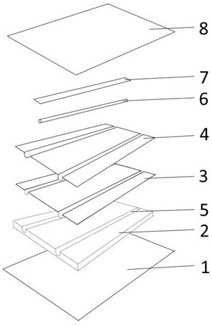
The invention discloses a laying method of nano carbon crystal water heating modules, and belongs to the technical field of floor heating equipment. The method comprises the following steps that multiple sets of keels parallel to one another are installed on a cement floor; then a floor heating heat reflecting film is laid between the keels; then, the nano carbon crystal water heating modules arelaid between the keels and on the floor heating reflecting film; then nailing and fixing are carried out; then, floor heating pipes are embedded into grooves of the nano carbon crystal water heating modules; an aluminum tape is pasted, the floor heating pipes are sealed; then, a non-woven fabric layer is laid, and the nano carbon crystal water heating modules are packaged; finally, supporting facilities such as a floor, a boiler, a temperature control panel and an electromagnetic valve are installed. According to the laying method of the nano carbon crystal water heating modules, water heatingpipes are adopted to replace an electric heating device, due to the fact that the specific heat capacity of water is relatively large, the temperature rising process is softer, the heat preservationtime is longer, the influence on the humidity of air is small, and the problems of heat energy superposition, power capacity increase, infrared radiation, comfort and the like caused by traditional electric floor heating are solved.

Description

technical field [0001] The invention belongs to the technical field of floor heating equipment, in particular to a laying method of a nano-carbon crystal water heating module. Background technique [0002] The existing central heating method needs to consume a lot of financial and material resources in the installation of the heating system, and the heat loss is relatively serious during the transmission process. Moreover, in most parts of the south, considering the climate, cost and other reasons, it is impossible to use the central heating system as a Heating method. The electric heating system, for example, directly installs electric heating elements (heating cables, carbon crystal plates, electric heating plates) under the floor for use, with its advantages of flexibility, easy adjustment, convenience, independence, and strong operability. [0003] However, after many years of research by the applicant, it was found that the electric heating system has the following pro...

Claims


Application Information

Patent Timeline
IPC IPC(8): F24D3/14F24D19/00B05D7/16B05D3/10B05D3/12B05D3/06
CPCB05D3/065B05D3/102B05D3/12B05D7/16B05D7/574B05D2202/25B05D2301/00B05D2320/00B05D2502/00B05D2504/00B05D2506/10F24D3/149F24D19/008B05D2420/01B05D2420/02B05D2420/03Y02B30/00
Inventor 窦波王孝荣
Owner 南京拓新冷暖科技有限公司
Learn More