Metal foil numerical control cutting and gluing direct forming additive manufacturing equipment and method

An additive manufacturing and metal foil technology, which is applied in the field of metal foil CNC cutting, gluing and direct forming additive manufacturing equipment, and can solve the problems of inability to form complex shapes, low efficiency, and thermal cracks.

Active Publication Date: 2020-10-30
SHENYANG AEROSPACE UNIVERSITY
View PDF7 Cites 4 Cited by
  • Summary
  • Abstract
  • Description
  • Claims
  • Application Information

AI Technical Summary

Problems solved by technology

The first five methods are traditional methods for forming metal structural parts, and their disadvantage is that they cannot form complex shapes; while 3D printing can produce metal parts with complex shapes, but because of the high temperature melting process, pores, thermal cracks and balls will also occur. Defects such as
The printing time is very long and the efficiency is very low, for example, it takes several hours for a mug
Most metal materials have to consider oxidation and other issues, and need to be printed in a vacuum, which limits the size of the workpiece

Method used


Image

  • Metal foil numerical control cutting and gluing direct forming additive manufacturing equipment and method
  • Metal foil numerical control cutting and gluing direct forming additive manufacturing equipment and method
  • Metal foil numerical control cutting and gluing direct forming additive manufacturing equipment and method

Examples


Embodiment 1

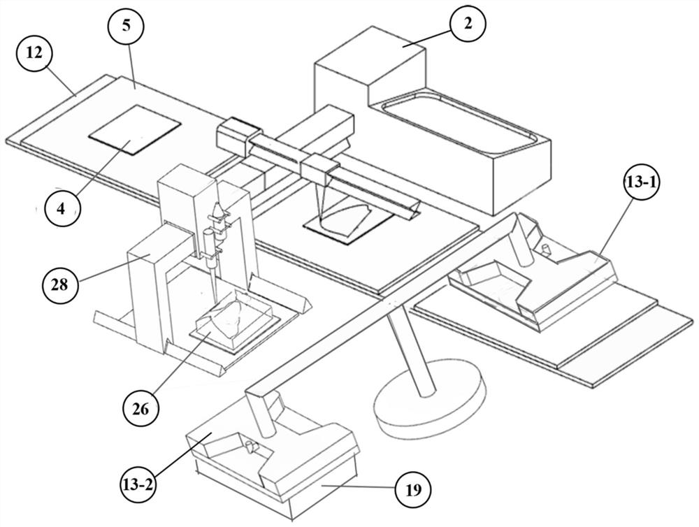
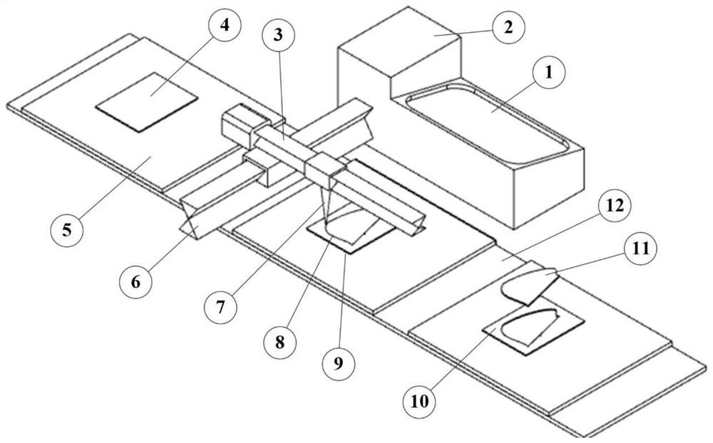
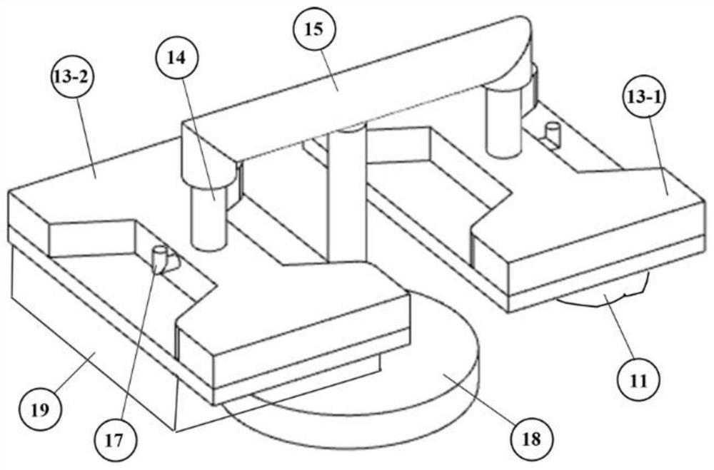
[0128] A metal foil CNC cutting and gluing direct molding additive manufacturing equipment, its overall structure schematic diagram is as follows figure 1 Therefore, a conveyor belt 12 is included, and the conveyor belt can control the transmission speed and circulation flow. A plurality of stainless steel plate processing tables 5 at equal distances are stuck on the conveyor belt. A laser cutting machine 2 is placed in the center of the conveyor belt. The laser cutting machine The experimental area can be passed by a conveyor belt. The laser cutting machine has a computer 1 that can be programmed or uploaded digitally. The laser cutting machine has a manipulator device 3, 6. The manipulator device includes an X axis 3 and a Y axis 6. , the X-axis and Y-axis are slidable axes, the X-axis of the manipulator has a rotatable laser beam 7, and a rotatable suction cup is placed on the side of the conveyor belt. The partial structure diagram of the device is as follows Figure 4 As ...

Embodiment 2

[0138] The device structure of the metal foil CNC cutting and gluing direct molding additive manufacturing technology in this embodiment is the same as that in Embodiment 1.

[0139] The additive manufacturing process of metal foil slices is the same as that of Example 1, the difference is that the GH4033 nickel-based superalloy metal foil is replaced with 316L stainless steel metal foil to carry out the additive manufacturing experiment of the thermos cup.

[0140] The experimental environment is the same as that of Example 1. A 316L stainless steel metal foil with a diameter of 100 mm and a thickness of 10 mm is placed in the center of the processing table, and is transported by a conveyor belt at a speed of 0.1 m / s, and is transmitted to the center of the laser cutting machine for 8 seconds. The processing route uploaded by the computer, the laser power is 10W, the scanning speed is 100mm / s, and the single-layer metal foil slice with a hollow layer is cut out for the thermos...

Embodiment 3

[0144] The device structure of the metal foil CNC cutting and gluing direct molding additive manufacturing technology in this embodiment is the same as that in Embodiment 1.

[0145] The additive manufacturing process of the metal foil slice is the same as that in Example 1, the difference is that the GH4033 nickel-based superalloy metal foil is replaced with the A356 aluminum alloy metal foil to carry out the additive manufacturing experiment of the wheel hub.

[0146] The experimental environment is the same as in Example 1. A356 aluminum alloy metal foil with a diameter of 550 mm and a thickness of 2 mm is placed in the center of the processing table, and is transported by a conveyor belt at a speed of 0.1 m / s, and is transmitted to the center of the laser cutting machine for 10 seconds. Program the processing route uploaded by the computer, the laser power is 10W, the scanning speed is 100mm / s, the hollow area of ​​the wheel hub is cut out, and the schematic diagram of the ...


PUM

PropertyMeasurementUnit
thicknessaaaaaaaaaa
thicknessaaaaaaaaaa
thicknessaaaaaaaaaa

Abstract

The invention discloses metal foil numerical control cutting and gluing direct forming additive manufacturing equipment and method. The equipment comprises a conveying belt, the conveying belt passesthrough a laser cutting machine, a digital programming route is arranged in the laser cutting machine, and a computer is combined with manipulators to complete a cutting station. A final workpiece issliced, programmed and digitally cut in advance, a special-shaped metal foil for additive manufacturing slicing is obtained, separation of waste and the metal special-shaped foil is completed throughsuction cups, and finally stacking operation of metal structural part is completed through gluing. Circular operation is carried out until a workpiece blank with a designed shape is obtained, and additive manufacturing is realized through curing. According to the method, the ultra-soft characteristic of the metal foil is utilized, and the metal structural part with the complex shape is stacked through layer-by-layer gluing under the cooperation of a mold. Compared with traditional additive manufacturing, the method has the advantages that the machining process is greatly shortened, and the cost is greatly reduced by using the metal foil with lower price. All waste materials are recycled in the whole manufacturing process, melting point temperature reaching and long-time heating forming arenot needed, energy is saved, and meanwhile pollution is reduced.

Description

Technical field: [0001] The invention belongs to the technical field of additive manufacturing, and in particular relates to a metal foil numerical control cutting and gluing direct molding additive manufacturing equipment and method. Background technique: [0002] Metal foil, which has a strong deformation ability, is usually manufactured by hammer forging or rolling, and most of them are made of materials with good ductility, such as aluminum, copper, tin and gold. It is mostly used in daily life, but if it is hypothermia caused by heat radiation, metal foil can also be used to reduce heat radiation to improve symptoms. Due to its limited post-forming method, the application of metal foil in different fields is limited, such as "hand-sheared steel" made by asynchronous rolling, and its thickness can reach 20 microns. [0003] At present, the forming methods of metal structural parts are generally casting, forging, rolling, extrusion, drawing, and 3D printing. Among them,...

Claims


Application Information

Patent Timeline
Patent Type & Authority Applications(China)
IPC IPC(8): B23K26/00B23K26/38B23K26/08B05D1/26B05C5/02B32B37/12B33Y30/00B33Y10/00B33Y40/00B33Y40/10B33Y40/20
CPCB23K26/0093B23K26/38B23K26/0884B05D1/26B05C5/0216B32B37/1284B33Y30/00B33Y10/00B33Y40/00B33Y40/10B33Y40/20Y02P70/10
Inventor 王悦王继杰王志伟农智升刘春忠马敔佟金玲杨家瑞刘兴民邓希光卢少微李壮
Owner SHENYANG AEROSPACE UNIVERSITY
Why Eureka
Try Eureka