
Glass kiln and method for heating glass batch

A glass furnace and batch material technology, which is applied in glass furnace equipment, glass production, glass manufacturing equipment, etc., can solve the problems of low yield of glass products, accelerated erosion of refractory materials, and increased costs

Active Publication Date: 2020-11-10
QINHUANGDAO GLASS IND RES & DESIGN INST
View PDF6 Cites 4 Cited by
  • Summary
  • Abstract
  • Description
  • Claims
  • Application Information

AI Technical Summary

Problems solved by technology

Although these means of melting help the melting of refractory glass, they will increase the production cost of glass and bring unsafe factors to the furnace. For example, electric boosting and pool bottom bubbling technology need Opening holes will increase the possibility of glass liquid leakage in the glass furnace, and the temperature at the opening part is relatively high. Opening holes will also speed up the erosion of refractory materials, increasing unsafe factors
Increasing the melting area is usually achieved by increasing the length and width of the glass furnace, which increases the cost of the furnace, increases the cost, and reduces the safety performance. The combustion system in the furnace also needs to be increased accordingly to meet the requirements of the entire furnace unit area. Requirements for the number of combustion systems and uniform temperature distribution
Adding a co-solvent to reduce the melting rate will make the melting quality of the glass worse, and the micro-defects of the central molten glass in the furnace and the surrounding glass molten are inconsistent, and the center is low and the two sides are high, which reduces the degree of homogenization of the glass, resulting in a low yield of glass products. Low

Method used


Image

  • Glass kiln and method for heating glass batch
  • Glass kiln and method for heating glass batch
  • Glass kiln and method for heating glass batch

Examples


Embodiment Construction

[0022] Existing air-assisted combustion glass furnaces include opposite side walls (i.e. parapets); a large sill (i.e. dome) placed on the top of the side walls and used to connect the opposite side walls to form the top of the glass kiln; The bottom of the glass is used to hold the melting pool of molten glass. When the glass furnace burns, the air preheated to a certain temperature (generally less than 1000°C) from the regenerator on this side enters the glass furnace through the small grate, meets the fuel in the flame space, and burns to generate high temperature, and the combustion products (i.e. smoke Gas) enters the regenerator on the opposite side and is discharged through the flue. The checker bricks in the regenerator on the opposite side store the heat in the flue gas. After the flue gas is discharged through the flue, the air used for combustion enters the side storage The checker bricks in the heat chamber and the regenerator use the heat collected in the flue gas...


PUM


Abstract

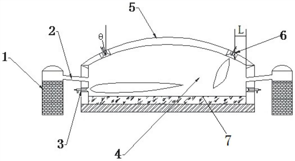
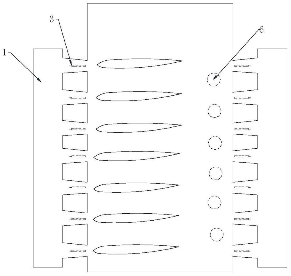
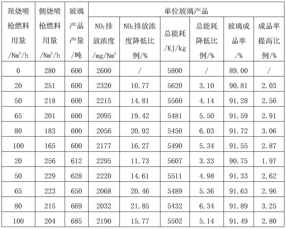
The invention discloses a glass kiln and a glass batch heating method thereof. The glass kiln comprises kiln side walls, a melting tank and a crown located above the melting tank and used for formingthe top of the glass kiln, wherein side burning spray guns are arranged on the opposite side walls of the glass kiln, and a plurality of top burning spray guns are further arranged on the two sides ofthe top of the crown respectively. According to the glass kiln, the burning spray guns are additionally arranged on the crown top, so that the flame ends alternately reach the set combustion area andcover the whole glass liquid level, continuous heating of the center combustion area is avoided, the NOX emission concentration and the total emission amount in smoke of the glass kiln are remarkablyreduced, energy consumption is reduced, and environmental pollution is reduced. The glass kiln with the new combustion mode provided by the invention is simple and stable in structure, simple in transformation of an existing kiln, low in investment and easy to popularize and apply in various combustion kilns taking air as combustion-supporting gas.

Description

technical field [0001] The invention relates to the technical field of glass production, in particular to a glass furnace and a method for heating glass batch materials with the glass furnace. Background technique [0002] The glass industry is a high energy consumption and high pollution industry, which consumes billions of tons of standard coal every year and produces a large amount of SO in the combustion process. 2 , NO X As well as harmful substances such as dust, it is easy to form acid rain and cause environmental pollution when discharged into the atmosphere. Ordinary float glass furnace with air as combustion gas, NO x The output is as high as 1800~3300mg / m 3 , SO 2 The output is as high as 2000~6000mg / m 3 . The latest air emission standard "GB26453-2011 Air Pollutant Emission Standard for Flat Glass Industry" requires SO 2 Emission concentration is not higher than 400mg / m 3 , NO X Emission concentration is not higher than 700mg / m 3 . At present, the end-...

Claims


Application Information

Patent Timeline
IPC IPC(8): C03B5/04C03B5/235C03B5/16
CPCC03B5/04C03B5/235C03B5/2353C03B5/16Y02P40/50
Inventor 刘成雄陈双七续芯如刘心明陈福冯建业
Owner QINHUANGDAO GLASS IND RES & DESIGN INST
Learn More