Method for reducing carbon-silicon contact resistance

A contact resistance, carbon-silicon technology, applied in circuits, fuel cells, electrical components, etc., can solve the problems of large contact resistance, reduced stack output power, and no discovery, and achieve high durability power density and good mechanical properties. , to ensure the effect of corrosion resistance

Pending Publication Date: 2020-11-10
浙江海晫新能源科技有限公司
View PDF12 Cites 1 Cited by
  • Summary
  • Abstract
  • Description
  • Claims
  • Application Information

AI Technical Summary

Problems solved by technology

With the further industrial application of the silicon pole plate, it will be found that the contact resistance between the silicon pole plate and the gas diffusion layer is relatively large, causing the fuel cell stack to consume energy due to its own internal resistance when generating electricity. The internal resistance of the stack not only reduces the output power of the stack, increases the heat generation and cooling burden, but also affects the life of the fuel cell stack due to the increase in the heat generated in the local area of ​​the fuel cell stack
For the fuel cell stack, the contact resistance between the bipolar plate and the gas diffusion layer is one of the main sources of the internal resistance of the stack. Therefore, reducing the contact resistance between the silicon plate and the gas diffusion layer is a key to manufacturing high-efficiency , high durability and high power density fuel cell stack; at the same time, after the applicant has conducted a large number of patent searches and technical information research, no relevant information on reducing the interface contact resistance between the silicon plate and the gas diffusion layer has been found. technology research
In addition, the surface of the silicon material bipolar plate is easy to form a natural oxide layer, which is hydrophilic, which is not conducive to the discharge of water generated during the operation of the fuel cell

Method used


Image

  • Method for reducing carbon-silicon contact resistance
  • Method for reducing carbon-silicon contact resistance
  • Method for reducing carbon-silicon contact resistance

Examples


Embodiment 1

[0038] Embodiment 1: A fuel cell stack, comprising not less than 3 fuel cell units connected in series and stacked as one; each fuel cell unit includes anode plates stacked in sequence, with Membrane electrode and cathode plate of the gas diffusion layer (made of carbon fiber); wherein,

[0039] The cathode plate and the anode plate are silicon plates made of doped conductive crystalline silicon material;

[0040] The silicon plate has an internal cooling medium flow channel, a front reducing agent flow channel and / or a reverse oxidant flow channel, and the internal cooling medium flow channel, the front reducing agent flow channel and / or the reverse oxidant flow channel are respectively provided with silicon Plate import and export combination;

[0041] Preferably, in this embodiment, the silicon plate includes 2 or more silicon chips, and the silicon chips have single-sided or double-sided flow channels; wherein, conductive materials are used between the surface areas of th...

Embodiment 2

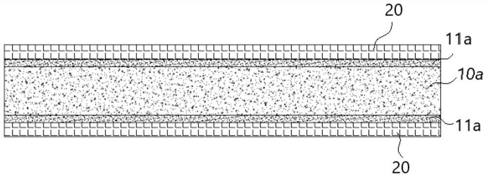
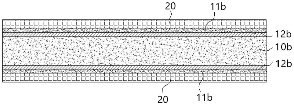
[0054] Embodiment 2: The remaining technical solutions of this embodiment 2 are the same as those of embodiment 1, the difference is that this embodiment 2 proposes a fuel cell stack with low contact resistance, between the silicon pole plate 10b and its corresponding gas diffusion layer 20 There is an intermediate layer used to reduce the contact resistance, and the intermediate layer is a deposited film formed by a deposition process; the contact resistance between the deposited film, the silicon plate and the gas diffusion layer is not greater than 10mΩ*cm 2 ; while the deposited film includes a carbon deposited film 11b in contact with its corresponding gas diffusion layer; wherein,

[0055] See figure 2 As shown, in this embodiment 2, the deposited film includes depositing the contacted carbon deposited film 11b and the metal deposited film 12b respectively, wherein, specifically, the deposition process of the metal deposited film 12b can adopt evaporation deposition or ...

Embodiment 3

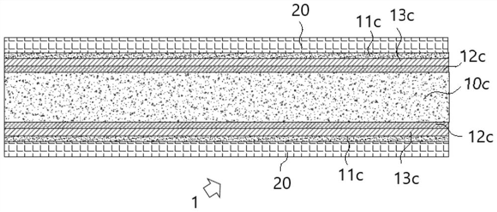
[0069] Embodiment 3: the remaining technical solutions of this embodiment 3 are the same as embodiment 2, the difference is that please refer to image 3 As shown, in this embodiment 3, the metal deposition film (material selection titanium) located on the silicon pole plate 10c is alloyed and heat-treated under the protection of an inert gas to form a metal-silicon alloy layer, and the silicon pole plate is transformed into an alloy for fuel cells Siliconized pole plate 1 is used to reduce the contact resistance between the silicon pole plate 10c and the carbon deposition film 11c; further specifically, in this embodiment 3, the surface of the silicon pole plate 10c is provided with a metal deposition film, and the surface of the silicon pole plate 10c is provided with a metal deposition film. The plate 10c is heat-treated so that the metal deposition film on the surface of the silicon pole plate 10c is alloyed (that is, the metal deposition film part is alloyed) to form a met...


PUM

PropertyMeasurementUnit
electrical resistivityaaaaaaaaaa
thicknessaaaaaaaaaa
thicknessaaaaaaaaaa

Abstract

The invention discloses a method for reducing the contact resistance of carbon and silicon, and the method employs a silicon plate which reduces the contact resistance between the silicon plate and acarbon film. The process comprises the following operation steps: S10) preparing a silicon plate, wherein the silicon plate is made of a doped conductive crystalline silicon material; S20) obtaining atransition deposition film and a carbon deposition film on the silicon plate through a deposition process, wherein the transition deposition film and the carbon deposition film are respectively formed through a single deposition process or once formed through a single deposition process. by arranging the structural design of the transition deposition film, the contact resistance between the silicon plate and the carbon deposition film is remarkably reduced.

Description

technical field [0001] The invention relates to the research field of carbon-silicon contact resistance, in particular to a method for reducing the carbon-silicon contact resistance, and the invention is especially suitable for application in the field of fuel cells. Background technique [0002] A fuel cell is a chemical device that directly converts the chemical energy of fuel into electrical energy, also known as an electrochemical generator. Since the fuel cell converts the Gibbs free energy in the chemical energy of the fuel into electrical energy through an electrochemical reaction, it is not limited by the Carnot cycle effect, and the energy conversion rate is high; and the reaction product of the fuel cell using hydrogen as fuel is Water, environmentally friendly, theoretically can achieve zero pollution emissions; in addition, the fuel cell has no mechanical transmission parts, less moving parts, and low noise during operation; moreover, the fuel cell also has high ...

Claims


Application Information

Patent Timeline
Patent Type & Authority Applications(China)
IPC IPC(8): H01M8/0228H01M8/0213
CPCH01M8/0213H01M8/0228Y02E60/50Y02P70/50
Inventor 秦臻王沛远杨克蒋朱景兵施正荣
Owner 浙江海晫新能源科技有限公司
Why Eureka
Try Eureka