Wastewater concentration and waste heat recycling device and method

A waste water concentration and waste water heater technology, which is applied in separation methods, feed water heaters, chemical instruments and methods, etc., can solve the problems of large heat loss, high energy consumption, and a large amount of high-quality steam, and achieve low operating costs and high energy efficiency. The effect of low consumption and low investment

Pending Publication Date: 2020-12-18
CHINA HUADIAN ENG +1
View PDF1 Cites 0 Cited by
  • Summary
  • Abstract
  • Description
  • Claims
  • Application Information

AI Technical Summary

Problems solved by technology

[0005] Therefore, the technical problem to be solved by the present invention is to overcome the defects in the prior art that desulfurization wastewater needs a large amount of high-quality steam, high energy consumption, and large heat loss to reduce and concentrate desulfurization wastewater, so as to provide a waste heat recovery device and method for wastewater concentration

Method used


Image

  • Wastewater concentration and waste heat recycling device and method
  • Wastewater concentration and waste heat recycling device and method
  • Wastewater concentration and waste heat recycling device and method

Examples


Embodiment 1

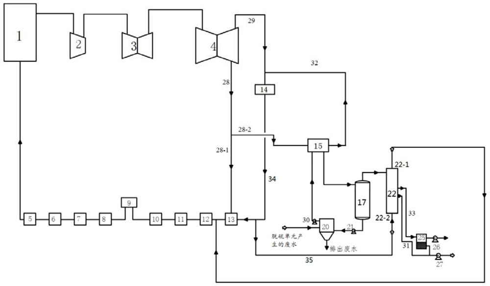
[0048] This embodiment provides a waste heat recovery device for waste water concentration, such as figure 1 As shown, including connected desulfurization unit, waste water concentration system and low-load condensate system;

[0049] The waste water concentrating system comprises a waste water heater 15, a flash tank 17, a first waste water transfer pump 21 and a waste water tank 20 connected in sequence, and the waste water tank 20 communicates with the waste water heater 15 through the second waste water transfer pump 30; in the waste water tank 20 A supernatant liquid outlet and a concentrated waste water outlet are provided, and at least one flash chamber is arranged in the flash tank 17. During normal operation of the device, the height of the waste water in the flash chamber is 5-50 cm, and the height is adjusted according to the waste water circulation amount; In the present embodiment, one flash chamber is arranged in the flash tank 17, the middle part of the flash ch...

Embodiment 2

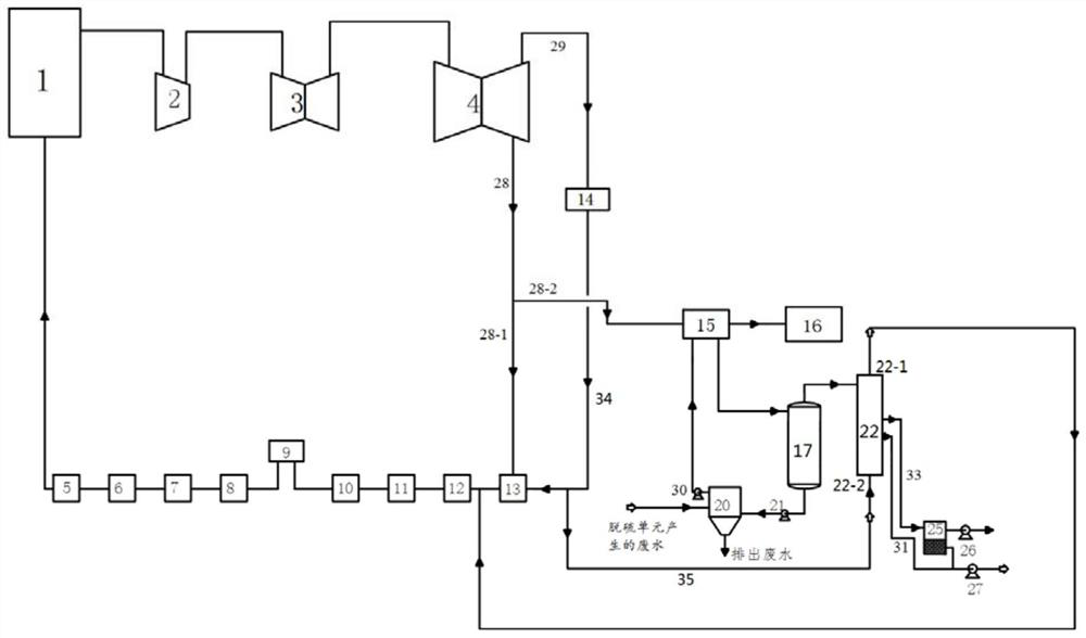
[0068] This embodiment provides a waste heat recovery method for waste water concentration, using image 3 provided means, comprising the following steps,

[0069] The generator set discharges the first heat exchange medium and the third heat exchange medium, the third heat exchange medium enters the condenser 14 through the second pipe 29, the steam condenses into water, and the first heat exchange medium enters through the first pipe 28 respectively In the first low heating heater 13 and the waste water heater 15;

[0070] The temperature of part of the steam from the generating set entering the waste water heater 15 is 97-99° C., which is used to heat the waste water from the waste water pool 20. The temperature of the waste water entering the waste water heater 20 is 33-37° C. After the waste water is heated, When the temperature reaches 65-95℃, it enters the flash tank for flash evaporation to obtain secondary steam, and the secondary steam enters the condenser, and the wa...


PUM


Abstract

The invention belongs to the technical field of wastewater treatment, and particularly relates to a wastewater concentration and waste heat recycling device and method. The wastewater concentration and waste heat recycling device comprises a desulfurization unit and a wastewater concentration system which communicate. The wastewater concentration system comprises a wastewater pool, a wastewater heater, a flash tank, a condenser and a low-pressure condensed water system which communicate. The low-pressure condensed water system communicates with the wastewater concentration system. The low-pressure condensed water system comprises a generator set, a condenser, a first low-pressure heater and a high-pressure heater. Heat discharged by the generator set can be used for heating wastewater in the wastewater heater, condensed water at an outlet of the condenser serves as a refrigerant to recycle heat of secondary steam, gradient utilization of the heat is achieved, the heat is returned to the low-pressure condensed water system through the wastewater concentration system, almost no heat is lost in the process, the heat required by desulfurization wastewater treatment is also satisfied, wastewater concentration is realized, and the defect that high-quality heat energy is consumed by utilizing a conventional route is overcome.

Description

technical field [0001] The invention belongs to the technical field of waste water treatment, and in particular relates to a waste heat recovery device and method for waste water concentration. Background technique [0002] The vast majority of power plants in my country use limestone wet desulfurization technology to remove sulfur dioxide in flue gas. The desulfurization wastewater generated during operation has become one of the most difficult wastewater to treat in coal-fired power plants due to its complex composition and many types of pollutants. At present, the chemical precipitation method is mainly used in China to treat desulfurization wastewater, commonly known as the three-box precipitation treatment method, but the water content of this method is high in salt and chloride ion content, and it is easy to cause secondary pollution after direct discharge. [0003] In order to achieve zero discharge of desulfurization wastewater, more and more scholars have begun to s...

Claims


Application Information

Patent Timeline
IPC IPC(8): F28B9/08F28D9/00F22D1/50C02F1/02C02F1/06C02F103/18
CPCC02F1/02C02F1/06C02F2103/18F22D1/50F28B9/08F28D9/00F28D2021/0022
Inventor 王争荣汪洋王凯亮吴冲耿宣苏军划何佳
Owner CHINA HUADIAN ENG
Why Eureka
Try Eureka