Preparation method and application of magnesium titanate/graphite-phase carbon nitride composite visible light photocatalyst

A graphite-phase carbon nitride and magnesium titanate technology, which is applied in the field of photocatalysis, can solve the problems of poor performance of visible light catalytic hydrogen production, small specific surface area, high photogenerated electron-hole recombination rate, and achieve high utilization rate of visible light, The effect of a wide range of visible light response

Inactive Publication Date: 2021-02-02
NANCHANG HANGKONG UNIVERSITY
View PDF4 Cites 6 Cited by
  • Summary
  • Abstract
  • Description
  • Claims
  • Application Information

AI Technical Summary

Problems solved by technology

[0003] The problem to be solved by the present invention is to provide a preparation method and application of a magnesium titanate / graphite-phase carbon nitride composite visible light catalyst, which can solve the problem of the small specific surface area of ​​the existing graphite-phase carbon nitride semiconductor material in photocatalysis and the photogenerated electrons. -Technical problems of high hole recombination rate and poor performance of visible light catalytic hydrogen production

Method used


Image

  • Preparation method and application of magnesium titanate/graphite-phase carbon nitride composite visible light photocatalyst
  • Preparation method and application of magnesium titanate/graphite-phase carbon nitride composite visible light photocatalyst
  • Preparation method and application of magnesium titanate/graphite-phase carbon nitride composite visible light photocatalyst

Examples


Embodiment 1

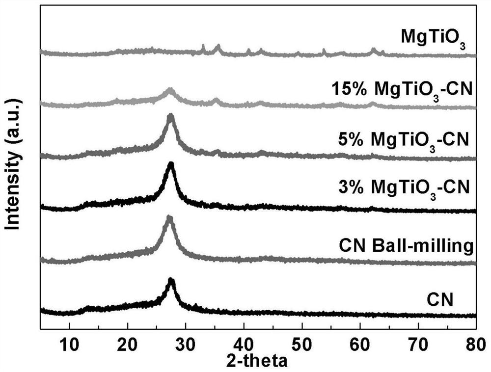
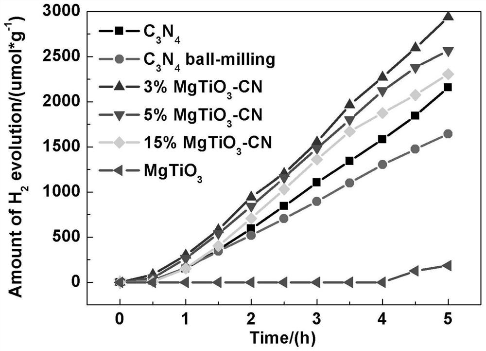
[0025] Step 1. Preparation of graphite phase carbon nitride powder: Weigh 20.000g of urea and grind it evenly into a crucible, cover the crucible and put it in a muffle furnace for calcination. The calcination process is as follows: from Heating at room temperature to 520°C, then keeping it warm at this temperature for 2 hours, cooling to room temperature naturally and grinding thoroughly to obtain graphite phase carbon nitride powder, denoted as C3N4;

[0026] Step 2. Preparation of perovskite magnesium titanate powder: Weigh 6.434g magnesium acetate tetrahydrate and place it in a beaker, measure 60.0mL ethylene glycol and add it to the weighed magnesium acetate tetrahydrate, use a 5.0mL pipette Add 3.4mL tetrabutyl titanate to the above solution, place it on a magnetic stirrer at room temperature and stir for 30 minutes, then put it into a reaction kettle, put the reaction kettle in an oven and heat it at 180±5°C for 24 hours, take it out and centrifuge it, and use it after c...

Embodiment 2

[0028] Embodiment 2: The difference from Example 1 is: in step 3, 0.025g of perovskite-type magnesium titanate powder is weighed, and the obtained magnesium titanate / graphite phase carbon nitride composite visible light catalyst is recorded as 5%MgTiO3 / g-CN.

Embodiment 3

[0029] Embodiment 3: The difference from Example 1 is: in step 3, 0.075g of perovskite-type magnesium titanate powder is weighed, and the obtained magnesium titanate / graphite phase carbon nitride composite visible light catalyst is recorded as 15%MgTiO3 / g-CN.


PUM


Abstract

The invention discloses a preparation method and application of a magnesium titanate/graphite-phase carbon nitride composite visible light photocatalyst. The invention aims to solve the technical problem of non-ideal photocatalytic activity caused by relatively high recombination rate of existing g-C3N4 photo-induced electron holes. The preparation method comprises the following steps: synthesizing g-C3N4 with a relatively high specific surface area by adopting a pyrolysis method, then preparing magnesium titanate with a perovskite structure by adopting a hydrothermal method, and finally preparing the magnesium titanate/g-C3N4 composite visible light photocatalyst by adopting a ball milling method. According to the photocatalytic material disclosed by the invention, semiconductors with different band gap energy levels are compounded to form a heterostructure, so that the photocatalytic material has an excellent and adjustable photo-induced electron hole separation rate and a relativelywide spectral response range under visible light, and can be applied to visible light catalytic hydrogen production in the field of energy sources.

Description

technical field [0001] The invention relates to the technical field of photocatalysis, in particular to a preparation method and application of a magnesium titanate / graphite phase carbon nitride composite visible light catalyst. Background technique [0002] The two critical problems of energy shortage and environmental pollution are becoming more and more serious, threatening the long-term stable development of human society more and more seriously. Governments and scientists of various countries are trying to find green and sustainable science and technology to solve the above problems. Hydrogen has high energy density, environmental friendliness and no secondary pollution. It is a renewable and clean energy with great development potential. Photocatalysis using semiconductor catalysts can generate hydrogen by photocatalytically splitting water with solar energy. It has been found that graphite phase carbon nitride (g-C3N4) has a special semiconductor energy band structu...

Claims


Application Information

Patent Timeline
Patent Type & Authority Applications(China)
IPC IPC(8): B01J27/24C01B3/04
CPCB01J35/004B01J27/24C01B3/042C01B2203/0277Y02E60/36
Inventor 罗一丹郑傲峰薛名山谢宇殷祚炷洪珍谢婵陈亮
Owner NANCHANG HANGKONG UNIVERSITY
Why Eureka
Try Eureka