Substrate integrated waveguide slot feed microstrip array antenna

A substrate-integrated waveguide and microstrip array technology, applied in the directions of antenna arrays, antennas, and antenna arrays that are energized separately, can solve the problems of parasitic radiation energy of transmission lines, affecting antenna gain, leakage, etc., to reduce parasitic radiation and energy. Leakage, increased gain, low loss effects

Pending Publication Date: 2021-02-02
三万星空(西安)信息技术有限公司
View PDF0 Cites 2 Cited by
  • Summary
  • Abstract
  • Description
  • Claims
  • Application Information

AI Technical Summary

Problems solved by technology

[0004] For example, the document "Design of 77 GHz Narrow Beamwidth Antenna for UAVs ObstacleAvoidance Radar" proposes the use of a microstrip-printed quasi-Yagi antenna array as a millimeter-wave obstacle avoidance radar antenna, and the document "3D-Sensing MIMO Radar for UAV Formation Flight and Obstacle Avoidance" proposes An obstacle avoidance radar applied to unmanned aerial vehicles, the antenna of the radar adopts the traditional microstrip antenna series feed array, but the existing technology uses the microstrip series feed antenna array for the millimeter wave radar antenna, which causes the parasitic radiation and the parasitic radiation on the transmission line. Energy leakage problem, affecting antenna gain

Method used


Image

  • Substrate integrated waveguide slot feed microstrip array antenna
  • Substrate integrated waveguide slot feed microstrip array antenna
  • Substrate integrated waveguide slot feed microstrip array antenna

Examples


Embodiment 1

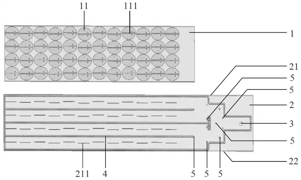
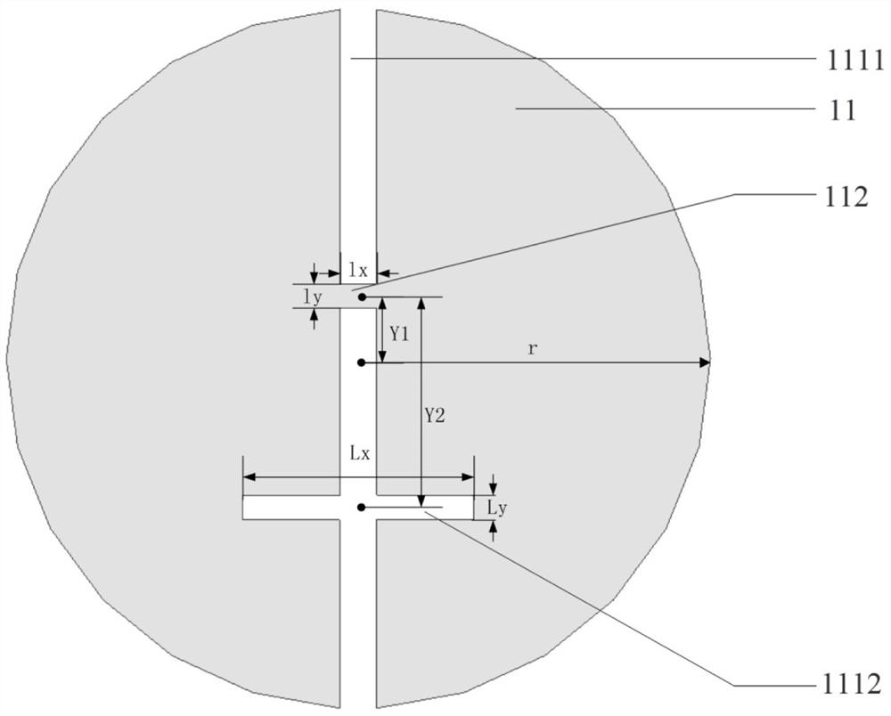
[0036] Example 1: Reference Figure 1~2 As shown, a substrate-integrated waveguide slot-fed microstrip array antenna includes an upper dielectric substrate 1 and a lower dielectric substrate 2. The upper dielectric substrate 1 is located directly above the left side of the lower dielectric substrate 2 and is connected to the lower dielectric substrate 2. connected; wherein, the upper surface of the upper dielectric substrate 1 is printed with 4×12 circular radiation patches 11 arranged periodically, and each circular radiation patch 1 is provided with the same cross-shaped grooves 111 of different lengths ; Change the current distribution on the circular radiation patch 11 by opening a cross-shaped slot, so as to achieve the purpose of reducing the reflection coefficient and increasing the gain.

[0037]Wherein, the cross-shaped groove 111 is composed of a long groove 1111 and a short groove 1112. The short groove 1112 is perpendicular to the long groove 1111 and arranged symm...

Embodiment 2

[0044] Embodiment 2: The circular radiation patch 11 printed on the upper surface of the upper dielectric substrate 1 is not subjected to groove processing (other parameters are the same).

[0045] Below in conjunction with simulation experiment, effect of the present invention is described as follows:

[0046] Simulation 1, utilize commercial simulation software HFSS_19.2 to carry out simulation calculation to the reflection coefficient of embodiment 1 of the present invention, the result is as follows Figure 5 shown; from Figure 5 It can be seen that near 24.7 GHz, the amplitude of the reflection coefficient of the antenna in Embodiment 1 of the present invention is less than -40 dB, indicating that there is better impedance matching in this frequency band.

[0047] Simulation 2, using commercial simulation software HFSS_19.2 to simulate the calculation of the normalized pattern curve at 24.1GHz in Embodiment 1 of the present invention, the results are as follows Image ...


PUM

PropertyMeasurementUnit
Lengthaaaaaaaaaa
Widthaaaaaaaaaa
Thicknessaaaaaaaaaa

Abstract

The invention discloses a substrate integrated waveguide slot feed microstrip array antenna, which comprises an upper dielectric substrate and a lower dielectric substrate, wherein the upper dielectric substrate is located right above the left side of the lower dielectric substrate and is connected with the lower dielectric substrate; the upper surface of the upper dielectric substrate is printedwith 4*12 periodically arranged circular radiation patches, and each circular radiation patch is provided with cross-shaped grooves with different lengths; the lower dielectric substrate is a substrate integrated waveguide slot array, good conductors are printed on the upper surface and the lower surface of the lower dielectric substrate, slots in one-to-one correspondence with the cross-shaped grooves are formed in the upper surface, and a plurality of metallized through holes and coaxial feed ports are formed in the middle of the lower dielectric substrate; in addition, the dielectric constants of the upper and lower dielectric substrates are different. The array antenna is compact in structure and reasonable in design, has the characteristics of high feed performance, high gain, miniaturization and the like, and can be used for obstacle avoidance millimeter-wave radar of a multi-rotor unmanned aerial vehicle platform.

Description

technical field [0001] The invention belongs to the technical field of antennas, and in particular relates to a substrate-integrated waveguide slot-fed microstrip array antenna, which can be used for obstacle avoidance millimeter-wave radar of a multi-rotor unmanned aerial vehicle platform. Background technique [0002] With the development of drone technology, multi-rotor drones have more and more applications in social life. The complex working environment puts forward higher and higher requirements on the form and performance of the antenna carried by the multi-rotor UAV platform. The multi-rotor UAV platform is greatly affected by the wind when it is working, and the carrying space is limited. Therefore, the antenna needs to be compact in structure, low in profile, light in weight, easy to integrate, and high in gain. The multi-rotor UAV obstacle avoidance radar antenna ensures the safety of the multi-rotor UAV when it is working, and further expands the application ran...

Claims


Application Information

Patent Timeline
IPC IPC(8): H01Q1/38H01Q1/50H01Q21/00H01Q21/06H01Q1/28
CPCH01Q1/285H01Q1/38H01Q1/50H01Q21/0006H01Q21/065
Inventor 杨大慰李瑞岚程通
Owner 三万星空(西安)信息技术有限公司
Why Eureka
Try Eureka