
Hazardous waste incineration flue gas treatment system and hazardous waste incineration flue gas treatment method

A hazardous waste and incineration flue gas technology, which is applied in the field of hazardous waste incineration flue gas treatment and hazardous waste incineration flue gas treatment system, can solve the problems of heater flue gas corrosion, flue gas heat loss, and high processing costs, and reduce emissions Concentration, increase the inlet air temperature, reduce the effect of oxygen concentration

Pending Publication Date: 2021-03-09
中广核工程有限公司 +3
View PDF5 Cites 8 Cited by
  • Summary
  • Abstract
  • Description
  • Claims
  • Application Information

AI Technical Summary

Problems solved by technology

[0004] Therefore, the flue gas treatment process of the general flue gas treatment scheme does not consider heat recovery, resulting in heat loss in the flue gas
At the same time, in order to avoid the phenomenon of "white smoke" in the flue gas at the chimney outlet, external steam is used to heat the flue gas after wet deacidification, resulting in waste of energy. At the same time, there are problems of flue gas corrosion and short service life of the heater.
The denitrification system with selective catalytic reduction method is added, the operating cost is high, and the used catalyst is hazardous waste, and the treatment cost is high

Method used


Image

  • Hazardous waste incineration flue gas treatment system and hazardous waste incineration flue gas treatment method
  • Hazardous waste incineration flue gas treatment system and hazardous waste incineration flue gas treatment method

Examples


Embodiment Construction

[0037] In order to have a clearer understanding of the technical features, purposes and effects of the present invention, the specific implementation manners of the present invention will now be described in detail with reference to the accompanying drawings.

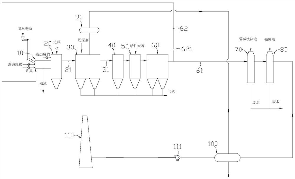
[0038] The hazardous waste incineration flue gas treatment system of the present invention is used for treating the flue gas produced by the rotary kiln incinerating hazardous waste, recovering heat from the flue gas and removing harmful substances therein.

[0039] Such as figure 1 As shown, the hazardous waste incineration flue gas treatment system according to an embodiment of the present invention includes a rotary kiln 10, a secondary combustion chamber 20, a waste heat boiler 30, a rapid cooling tower 40, and a dry deacidification tower 50 sequentially connected along the direction of progress of the flue gas. , dust collector 60, washing tower 70 and wet deacidification tower 80.

[0040] Among them, the rotary ...


PUM


Abstract

The invention discloses a hazardous waste incineration flue gas treatment system and a hazardous waste incineration flue gas treatment method. The hazardous waste incineration flue gas treatment system comprises a rotary kiln, a secondary combustion chamber, a waste heat boiler, a quench tower, a dry deacidification tower, a dust remover, a washing tower, a wet deacidification tower and a flow dividing flue, wherein the rotary kiln, the secondary combustion chamber, the waste heat boiler, the quench tower, the dry deacidification tower, the dust remover, the washing tower and the wet deacidification tower are sequentially connected in the advancing direction of flue gas; and the flow dividing flue is connected between an outlet of the dust remover and the rotary kiln. The flue gas generated by incineration of the rotary kiln is treated, the flue gas meets the low-nitrogen emission requirement, and meanwhile the problem about flue gas heat recovery after incineration of the rotary kilnis solved; and part of the flue gas is guided into the rotary kiln through the flow dividing flue to be recycled in the subsequent treatment process, the air inlet temperature of the rotary kiln is increased, the oxygen concentration of the rotary kiln is reduced, and then the emission concentration of nitric oxide is reduced.

Description

technical field [0001] The invention relates to the technical field of hazardous waste treatment, in particular to a hazardous waste incineration flue gas treatment system and a hazardous waste incineration flue gas treatment method. Background technique [0002] At present, the main furnace types used for hazardous waste incineration at home and abroad include rotary kiln incinerator, grate furnace, liquid injection incinerator, fluidized bed incinerator, multi-layer bed incinerator and pyrolysis incinerator, etc. The incineration process of hazardous waste More complex, rotary kiln is widely used due to its simple structure, strong adaptability to hazardous waste, stable control, easy operation, mature technology, and long operating history. The flue gas produced by incineration needs to be purified because it contains harmful substances such as sulfur dioxide, nitrogen oxides, hydrogen chloride, hydrogen fluoride, heavy metals, dust, and dioxins. The temperature of the f...

Claims


Application Information

Patent Timeline
Patent Type & Authority Applications(China)
IPC IPC(8): F23G5/14F23G5/20F23G5/44F23G5/46F23J15/02F23J15/04F23J15/08
CPCF23G5/14F23G5/20F23G5/44F23G5/46F23J15/025F23J15/04F23J15/08Y02E20/30
Inventor 陈齐平代恩岩谢陈平严庆云潘国栋王增琛卢照升田智威陈惠敏
Owner 中广核工程有限公司
Learn More