Ceramic matrix composite satellite lightweight structural member surface flatness treatment method and structural member

A treatment method and a technology for structural parts, which are applied in the direction of pretreatment surface, device for coating liquid on the surface, coating, etc., can solve problems such as unsatisfactory parallelism, increased processing difficulty, and high hardness of silicon carbide materials, and achieve reduction Difficulty of machining, improvement of machining accuracy, uniform appearance and color

Pending Publication Date: 2021-03-16
XIAN XINGUI CERAMIC COMPOSITE MATERIAL CO LTD
View PDF3 Cites 2 Cited by
  • Summary
  • Abstract
  • Description
  • Claims
  • Application Information

AI Technical Summary

Problems solved by technology

[0003] The purpose of the present invention is to solve the problem that the flatness and parallelism of the installation and positioning end faces of the structural parts cannot meet the requirements of use in the production process of the ceramic matrix composite satellite lightweight structural parts existing in the prior art due to multiple CVI chemical vapor depositions. On-line processing is required, but the hardness of silicon carbide material is high, and general mechanical processing is difficult to meet the flatness requirements, and high-precision scraping and grinding cannot be performed, which leads to increased processing difficulty and difficult to guarantee product quality. Surface Flatness Treatment Method of Ceramic Matrix Composite Satellite Lightweight Structural Parts and Ceramic Matrix Composite Satellite Lightweight Structural Parts

Method used


Image

  • Ceramic matrix composite satellite lightweight structural member surface flatness treatment method and structural member
  • Ceramic matrix composite satellite lightweight structural member surface flatness treatment method and structural member
  • Ceramic matrix composite satellite lightweight structural member surface flatness treatment method and structural member

Examples


Embodiment 1

[0045] This embodiment is the processing of the surface flatness of the front lens tube of the optical remote sensing satellite, and the specific steps are as follows:

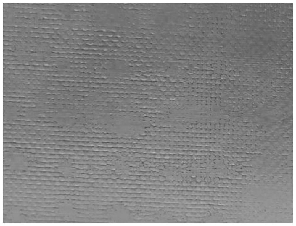
[0046] 1) Machining the surface of the front lens barrel that has been deposited after assembly to initially improve the flatness of the product surface, that is, using a diamond tool to grind the surface of the front lens barrel to reduce the surface flatness error to about 0.1mm, The ground surface as figure 1 shown. Due to the high hardness of the product material, machining is difficult, so the surface flatness error of the machined product does not meet the product precision requirements.

[0047] 2) Clean the surface of the front lens barrel, wash and dry it.

[0048] 3) Take epoxy resin glue and diluent, mix according to the mass ratio of 4:1, and stir until uniform without air bubbles to obtain glue, and the diluent is industrial ethanol.

[0049] 4) Add zirconium carbide powder to the glue, and sti...

Embodiment 2

[0057] This embodiment is the processing of the surface flatness of the front lens tube of the optical remote sensing satellite, and the specific steps are as follows:

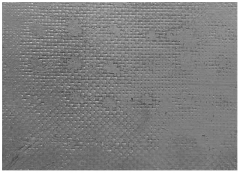
[0058] 1) Machining the surface of the front lens barrel that has been deposited after assembly to initially improve the flatness of the product surface, that is, using a diamond tool to grind the surface of the front lens barrel to reduce the surface flatness error to about 0.1mm, The ground surface as image 3 shown. Due to the high hardness of the product material, machining is difficult, so the surface flatness error of the machined product does not meet the product precision requirements.

[0059] 2) Clean the surface of the front lens barrel, wash and dry it.

[0060] 3) Take epoxy resin glue and diluent, mix according to the mass ratio of 5:1, and stir until uniform without air bubbles to obtain glue, and the diluent is industrial ethanol.

[0061] 4) Add zirconium carbide powder to the glue, and sti...

Embodiment 3

[0069] This embodiment is the processing of the surface flatness of the front lens tube of the optical remote sensing satellite, and the specific steps are as follows:

[0070] 1) Machining the surface of the front lens barrel that has been deposited after assembly to initially improve the flatness of the product surface, that is, using a diamond tool to grind the surface of the front lens barrel to reduce the surface flatness error to about 0.1mm, The ground surface as Figure 5 shown. Due to the high hardness of the product material, machining is difficult, so the surface flatness error of the machined product does not meet the product precision requirements.

[0071] 2) Clean the surface of the front lens barrel, wash and dry it.

[0072] 3) Take epoxy resin glue and diluent, mix according to the mass ratio of 6:1, and stir until uniform without air bubbles to obtain glue, and the diluent is industrial ethanol.

[0073] 4) Add zirconium carbide powder to the glue, and st...


PUM

PropertyMeasurementUnit
hardnessaaaaaaaaaa
thicknessaaaaaaaaaa
thicknessaaaaaaaaaa

Abstract

The invention relates to a ceramic matrix composite satellite lightweight structural member surface flatness treatment method and a ceramic matrix composite satellite lightweight structural member, and aims to solve the problems that the flatness requirement is difficult to meet by general machining and high-precision scraping cannot be performed due to relatively high material hardness of the ceramic matrix composite satellite lightweight structural member, the processing difficulty is increased, and the product quality is difficult to guarantee. The ceramic matrix composite satellite lightweight structural member surface flatness treatment method comprises the following steps: carrying out preliminary machining, cleaning and drying on the surface of the ceramic matrix composite satellitelightweight structural member; smearing a glue solution prepared from epoxy resin glue on the surface of the ceramic matrix composite satellite lightweight structural member; carrying out super-finish machining on the surface of a glue layer after the glue solution is cured to form the glue layer; and finally, scraping to enable the surface flatness of the structural member to meet the requirement. The structural member manufactured through the ceramic matrix composite satellite lightweight structural member surface flatness treatment method has the advantages that the surface flatness meetsthe design and use requirements, and the performance is good.

Description

technical field [0001] The invention relates to a method for processing the surface flatness of a ceramic-matrix composite material satellite light-weight structural part and a ceramic-matrix composite material satellite light-weight structural part. Background technique [0002] Ceramic matrix composite material (ceramic matrix composite material) is a new thermal structure / functional integrated material with the advantages of metal materials, ceramic materials and carbon materials. It has high temperature resistance, low density, high specific strength, high specific modulus , Anti-oxidation, anti-ablation, anti-radiation, insensitive to cracks, and no catastrophic damage, etc., it has a wide range of applications in machinery, aerospace, nuclear, energy and other fields. The production process of ceramic matrix composite satellite lightweight structural parts includes parts, components, assembly of components, CVI chemical vapor deposition, online machining and other proc...

Claims


Application Information

Patent Timeline
Patent Type & Authority Applications(China)
IPC IPC(8): B05D7/00B05D3/02B05D3/04B24B1/00C09D163/00C09D7/61
CPCB05D7/00B05D3/0254B05D3/0406B24B1/00C09D163/00C09D7/61C09D7/70B05D2504/00B05D2301/00B05D2203/30C08K3/14C08K7/10
Inventor 张建平吕雉赵兵兵马渊张少博吴亚明赵晖李仁意
Owner XIAN XINGUI CERAMIC COMPOSITE MATERIAL CO LTD
Why Eureka
Try Eureka