Direct injection natural gas engine system based on ammonia pyrolysis device and control method of direct injection natural gas engine system

An engine system and natural gas technology, applied in engine control, electrical control, charging system, etc., can solve problems affecting the measurement and control accuracy of consumption rate, elimination of after-treatment system, high HC emission, etc., to improve combustion characteristics and emission characteristics , Reduce energy consumption, reduce the effect of HC emissions

Active Publication Date: 2021-06-04
HEBEI UNIV OF TECH
View PDF28 Cites 10 Cited by
  • Summary
  • Abstract
  • Description
  • Claims
  • Application Information

AI Technical Summary

Problems solved by technology

After the partial premixed combustion mode is adopted, although the thermal efficiency and soot emission of the high-pressure direct injection natural gas engine can be improved, the emission of HC (hydrocarbons) has increased, and the main component of HC emission is methane, which is difficult to eliminate through the post-treatment system
[0003] The literature "Li Menghan, Zhang Qiang, Li Guoxiang, Shao Sidong. Research on the combustion parameters of the external characteristics of the high-pressure direct injection natural gas engine in the cylinder [J]. Natural gas pressure fluctuations will affect the measurement and control accuracy of its consumption rate
Literature "Li, Menghan, Zheng, Xuelong, Liu, Xiaori, et al(2130). The effects of partially premixed combustion mode on the performance and emissions of a direct injection natural gas engine, Fuel, 2130, 260:228-245." The combustion and emission characteristics of the partial premixed combustion mode are disclosed in the high-pressure direct injection natural gas engine. The main defect of the partial premixed combustion mode is that the HC emission is too high

Method used


Image

  • Direct injection natural gas engine system based on ammonia pyrolysis device and control method of direct injection natural gas engine system

Examples


Embodiment Construction

[0022] Specific examples of the present invention are given below. The specific embodiments are only used to further describe the present invention in detail, and do not limit the protection scope of the claims of the present application.

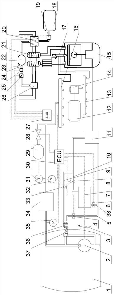
[0023] The present invention provides a direct-injection natural gas engine system (engine system for short) based on an ammonia pyrolysis device, the engine system includes an LNG tank 1, a diesel tank 12, a diesel rail 13, a high-pressure diesel pump 14, and a high-pressure direct-injection natural gas engine 15 , high-pressure natural gas rail 16, concentric biaxial needle injector 17, turbocharger 21, buffer tank stop valve 28, buffer tank 29, engine electronic control unit 30, natural gas temperature sensor 31, natural gas pressure sensor 32 and LNG vaporizer 34;

[0024] The high-pressure direct-injection natural gas engine 15 is provided with a concentric biaxial needle injector 17 and a turbocharger 21; the high-pressure natural gas...


PUM


Abstract

The invention discloses a direct injection natural gas engine system based on an ammonia pyrolysis device and a control method of the direct injection natural gas engine system. The engine system comprises an LNG boost pressure regulation and control device, an ammonia pyrolysis device and an ammonia pyrolysis device electric control unit. The control method comprises the steps of controlling the fuel gas supply process and controlling the ammonia pyrolysis device. According to the ammonia pyrolysis device, catalytic pyrolysis of ammonia is achieved, liquid ammonia is converted into ammonia pyrolysis gas, the ammonia pyrolysis gas is introduced into a gas inlet system of a high-pressure direct injection natural gas engine, a proper amount of the ammonia pyrolysis gas is supplied to an engine cylinder in the gas inlet process of the engine, the ammonia pyrolysis gas is optimized, combustion in the cylinder is improved, HC emission is reduced, and the high emission standard is met; and according to the LNG boost pressure regulation and control device, the original plunger pump boosting mode is improved into the combined application of an internal gear pump and the LNG boost pressure regulation and control device, and the high-pressure direct injection natural gas engine works under the working conditions of the optimal LNG boost pressure and the optimal LNG flow according to the pressure and the flow.

Description

technical field [0001] The invention belongs to the field of in-cylinder high-pressure direct-injection natural gas engines, in particular to a direct-injection natural gas engine system based on an ammonia pyrolysis device and a control method thereof. Background technique [0002] The main component of natural gas is methane, which is a clean vehicle fuel. In-cylinder high-pressure direct-injection natural gas engine pressurizes and vaporizes LNG to obtain high-pressure natural gas. The high-pressure natural gas is directly injected into the cylinder to realize diffusion combustion, which has the advantages of high thermal efficiency and low emission. In order to reduce the soot emission of high-pressure direct-injection natural gas engines, the latest high-pressure direct-injection natural gas engines adopt a partial premixed combustion mode, through the pre-injection of natural gas, to improve the mixing degree of natural gas / air. After the partial premixed combustion m...

Claims


Application Information

Patent Timeline
Patent Type & Authority Applications(China)
IPC IPC(8): F02B69/04F02M21/02F02M63/02F02M25/12F02D19/08F02D41/00F02D41/38F01N5/02B01J19/00
CPCF02B69/04F02M21/0215F02M21/0218F02M21/0245F02M63/02F01N5/02F02M25/12F02D19/08F02D41/0025F02D41/38B01J19/0006B01J19/0013F02D2041/389Y02T10/30Y02T10/12
Inventor 李孟涵刘鑫吴撼明刘晓日张铁臣魏张宁
Owner HEBEI UNIV OF TECH
Why Eureka
Try Eureka