
Lithium niobate film double-Y-branch optical waveguide modulator adopting curve optical waveguide connection

An optical waveguide, lithium niobate technology, applied in nonlinear optics, optics, instruments, etc., can solve the problems of affecting the zero bias stability of the fiber optic gyroscope, increasing the chip space size, and increasing the loss of the waveguide, and reducing the bending radius. , the size reduction, the effect of increasing the refractive index difference

Active Publication Date: 2021-06-15
THE 44TH INST OF CHINA ELECTRONICS TECH GROUP CORP
View PDF19 Cites 1 Cited by
  • Summary
  • Abstract
  • Description
  • Claims
  • Application Information

AI Technical Summary

Problems solved by technology

This phase difference is very sensitive to temperature, which will cause crosstalk and noise in the optical path, and affect the bias stability of the fiber optic gyroscope
[0005] Existing double Y-branch optical waveguide phase modulators mainly use diffused optical waveguide technology (proton exchange process / titanium diffusion process) to manufacture double Y-branch optical waveguides, because the refractive index difference Δn between the waveguide layer and the base layer is small, generally only 0.01 ~0.04, the ability to bind light is weak, resulting in a large bending radius of the lithium niobate diffused optical waveguide (too small a bending radius will lead to a sharp increase in waveguide loss)
At the same time, due to the large bending radius of the lithium niobate diffused optical waveguide, the overall space occupied by the chip is greatly increased.

Method used


Image

  • Lithium niobate film double-Y-branch optical waveguide modulator adopting curve optical waveguide connection
  • Lithium niobate film double-Y-branch optical waveguide modulator adopting curve optical waveguide connection
  • Lithium niobate film double-Y-branch optical waveguide modulator adopting curve optical waveguide connection

Examples


Embodiment Construction

[0024] In order to enable those skilled in the art to better understand the technical solutions in the embodiments of the present invention, and to make the above-mentioned purposes, features and advantages of the embodiments of the present invention more obvious and understandable, the following describes the technical solutions in the embodiments of the present invention in conjunction with the accompanying drawings For further detailed explanation.

[0025] In the description of the present invention, unless otherwise specified and limited, it should be noted that the term "connection" should be understood in a broad sense, for example, it can be a mechanical connection or an electrical connection, or it can be the internal communication of two elements, it can be Directly connected or indirectly connected through an intermediary, those skilled in the art can understand the specific meanings of the above terms according to specific situations.

[0026] like image 3 , Fi...


PUM

PropertyMeasurementUnit
thicknessaaaaaaaaaa
thicknessaaaaaaaaaa
radiusaaaaaaaaaa

Abstract

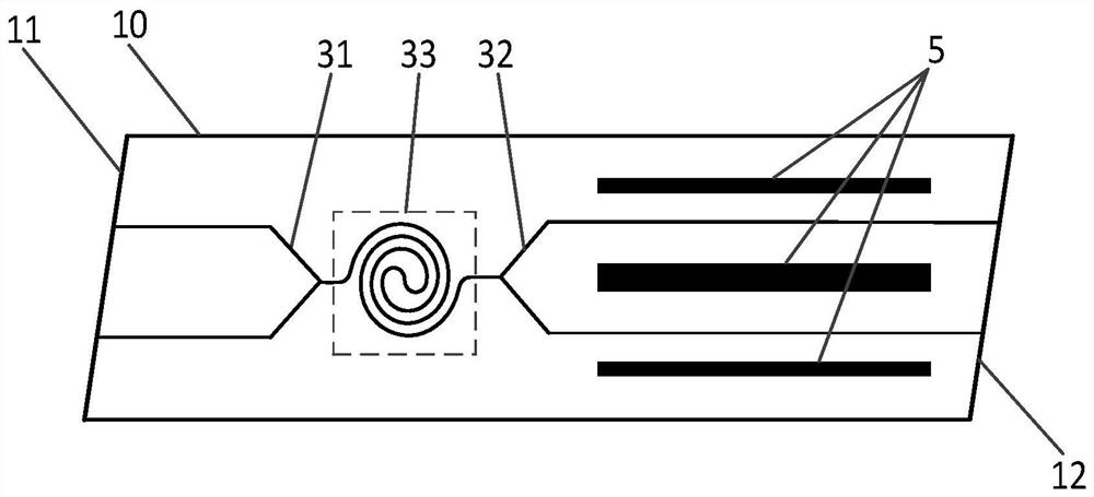
The invention discloses a lithium niobate film double-Y-branch optical waveguide modulator adopting curve optical waveguide connection, which comprises a double-Y-branch optical waveguide phase modulator chip, wherein the double-Y-branch optical waveguide phase modulator chip comprises a substrate, the substrate is sequentially provided with a silicon dioxide layer, an optical waveguide layer and a protective layer, and a modulation electrode is arranged on the protective layer; and the optical waveguide layer comprises a lithium niobate thin film layer and a lithium niobate ridge-shaped optical waveguide of a double-Y-branch optical waveguide structure, and a transition optical waveguide connecting the two Y-branch optical waveguides is a curve waveguide. According to the lithium niobate film double-Y-branch optical waveguide modulator, the transition optical waveguide adopts a curve structure, so that the problems of crosstalk and noise caused by coupling of a radiation mode in an optical path are effectively eliminated; besides, by changing the structure of the lithium niobate film optical waveguide chip, the refractive index difference between the lithium niobate ridge-shaped optical waveguide and the protective layer is increased, the light binding capacity is further enhanced, the bending radius of the optical waveguide is greatly reduced, and miniaturization of the double-Y-branch optical waveguide modulator is achieved.

Description

technical field [0001] The invention relates to the field of optical waveguide phase modulators, in particular to a lithium niobate film double Y branch optical waveguide modulator connected by curved optical waveguides. Background technique [0002] The fiber optic gyroscope is an angular velocity sensing instrument based on the Sagnac phase shift effect. It has a series of advantages such as all solid-state structure, small size, anti-electromagnetic interference, high precision and long life. like figure 1 As shown, the fiber optic gyroscope is composed of a low-coherence light source, a fiber coupler, a Y waveguide phase modulator, a polarization-maintaining fiber ring, a photodetector, and a signal processing circuit. The optical components are connected by pigtail fusion to form a closed optical path. The circuit part adopts an all-digital closed-loop detection scheme. When the polarization-maintaining optical fiber ring rotates at an angular rate Ω relative to the i...

Claims


Application Information

Patent Timeline
Patent Type & Authority Applications(China)
IPC IPC(8): G02F1/035G02F1/03G01C19/72
CPCG02F1/035G02F1/0305G01C19/721
Inventor 田自君郑帅峰陈诚文利
Owner THE 44TH INST OF CHINA ELECTRONICS TECH GROUP CORP
Learn More