Thrust pad repairing method based on laser cladding process

A laser cladding and repair method technology, applied in the field of bearings, can solve the problems of poor flatness of steel billet and babbitt alloy layer, difficulty in control, large heat input, etc., and achieve good forming accuracy, good performance and low heat input small effect

Pending Publication Date: 2021-06-18
CHINA YANGTZE POWER
View PDF6 Cites 2 Cited by
  • Summary
  • Abstract
  • Description
  • Claims
  • Application Information

AI Technical Summary

Problems solved by technology

[0003] The thrust pad of the hydraulic turbine is different from the traditional bearing pad. It is a plane thrust bearing, which bears the weight of the rotating part of the entire unit and the axial water thrust. After long-term use, defects such as scratches, wear, and shrinkage holes will be exposed, which will affect the normal operation of the unit. operation, must be replaced in time
At present, there is no effective repair method for the thrust tiles that have failed to be replaced. The traditional Babbitt casting process is complicated, and this method has the following defects:
[0004] 1. The pouring process includes billet preheating, tinning, babbitt melting, mold making preparation, babbitt pouring, cooling, defect repair, etc. The process is complicated
[0005] 2. The process of hanging tin in the pouring process is the key to the combination of Babbitt alloy and steel billet. It is not easy to control. Improper control can easily lead to shelling of the Babbitt alloy layer, and the tinning is through the chemical reaction between tin and the surface of the billet. In this case, the bonding method is chemical bonding, the bonding layer is thin, and the bonding force is not reliable.
[0006] 3. The pouring of Babbitt alloy requires a long period of solidification and cooling process, which is prone to shrinkage and shrinkage defects
[0007] 4. In the babbitt alloy pouring process, the heat input is large, the thermal deformation of the billet is large, the flatness of the billet and the babbitt alloy layer is poor, and the amount of machine addition is large
If the temperature is too low, a good tinning layer cannot be formed; if the temperature is too high, the steel bottom of the thrust tile is easily oxidized, and the tinning is not easy to bond, resulting in the Babbitt alloy being unable to be effectively combined with the tile bottom, resulting in shelling defects, and the quality is difficult to obtain. ensure

Method used


Image

  • Thrust pad repairing method based on laser cladding process
  • Thrust pad repairing method based on laser cladding process
  • Thrust pad repairing method based on laser cladding process

Examples


Embodiment 1

[0045] like figure 1 , the repair method of the thrust tile specifically includes the following steps:

[0046] 1) Preprocess the thrust tile to be repaired to remove the original babbitt alloy layer on the thrust tile;

[0047] 2) Clean the pretreated steel billet 1 with an organic solvent to remove oil contamination on the surface of the steel billet 1;

[0048] 3) Place the SnSb8-8 babbitt powder in an oven at 60°C for 2.5h for drying;

[0049] 4) Using the dried babbitt powder as the raw material, the new babbitt layer is additively manufactured on the billet 1 by means of laser cladding;

[0050] 5) Semi-finishing milling of the surface of the new babbitt alloy layer, the milling amount of semi-finishing milling is controlled to be leveled on the surface of the babbitt alloy layer to ensure that there is still enough machining allowance for the babbitt alloy layer of the thrust pad

[0051] 6) Use ultrasonic flaw detection technology to perform ultrasonic flaw detectio...

Embodiment 2

[0062] On the basis of Example 1, the following steps are used to carry out the laser cladding operation described in step 4):

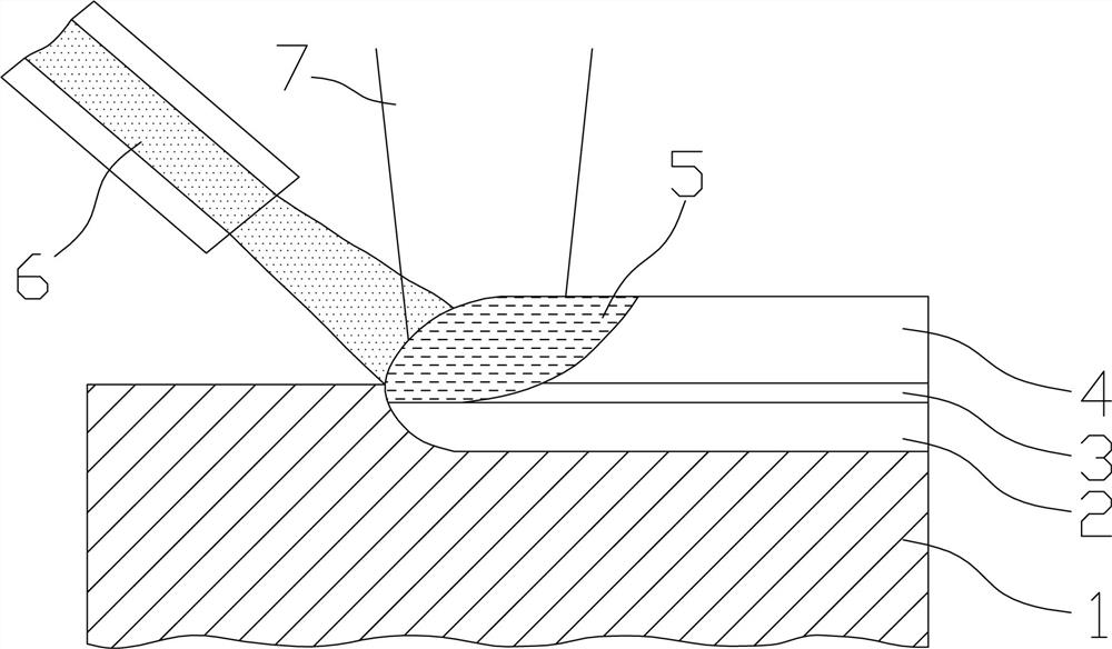
[0063] 1) A laser 7 is generated by a laser transmitter as a heat source, and the surface of the billet 1 is irradiated to form a molten pool 5;

[0064] 2) The powder-containing gas stream 6 is sent into the molten pool 5 through the gas powder feeding equipment for rapid melting;

[0065] 3) Remove the laser emitter and partially solidify the molten powder to form a solidified layer 4.

[0066] In a preferred solution, a bonding layer 3 is formed between the solidified layer 4 and the steel billet 1 .

[0067] In a preferred solution, the surface of the steel billet 1 is irradiated by the laser 7 to form a heat-affected zone 2 , and the output direction of the powder-containing airflow 6 faces the heat-affected zone 2 .

[0068] In this example, the parameters of the laser cladding operation are as follows:

[0069] The rectangular laser spot is...

Embodiment 3

[0071] On the basis of Example 2, by controlling the movement of the robotic arm, the laser generator and the powder feeding mechanism are driven to translate on the surface of the billet 1, and the laser cladding additive manufacturing of the babbitt alloy is completed.

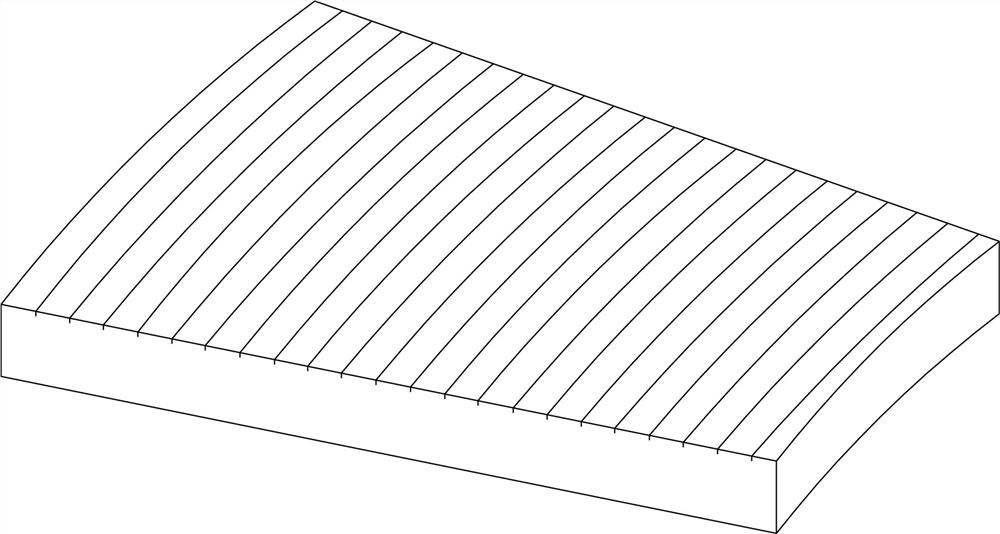
[0072] In this example, the laser cladding is completed along the arc edge, back and forth in both directions, a total of 3 layers are clad, to ensure that the thickness of the babbitt layer produced by the laser cladding additive manufacturing is about 3.3mm, and the overall thickness of the thrust pad is about 55.8mm (such as image 3 ).


PUM

PropertyMeasurementUnit
thicknessaaaaaaaaaa

Abstract

The invention aims at providing a thrust pad repairing method based on a laser cladding process. The deformation amount in the thrust pad repairing process is effectively controlled, the problems of hole shrinkage and shelling of a babbitt metal layer are thoroughly solved, the design size of a thrust pad is recovered, the use performance of the thrust pad is improved, the service life of the thrust pad is prolonged, and extremely high economical efficiency is achieved. The thrust pad repairing method comprises the following steps: removing an original babbitt metal layer of the thrust pad, preparing the babbitt metal layer on the surface of a steel billet through laser cladding, carrying out ultrasonic flaw detection, milling, carrying out dye penetrant inspection and grinding. According to the method, the thrust pad which fails in service is remanufactured, and the use performance of the thrust pad is recovered and improved through a new additive manufacturing method. Compared with pouring and oxyacetylene welding processes, the manufacturing process of the babbitt metal layer is greatly simplified, the steel billet preheating and tinning processes are omitted, and the quality of the babbitt metal layer, the combination condition of the babbitt metal layer and the steel billet, the deformation amount of the steel billet and the labor environment are effectively improved.

Description

technical field [0001] The invention relates to the field of bearings, in particular to a thrust pad repair method based on a laser cladding process. Background technique [0002] Babbitt is named after the invention of American Babbitt. Since its inception, babbitt has been widely recognized as a material with excellent performance because of its good wear resistance, thermal conductivity and special structure. It is beneficial to reduce friction, so it is widely used as a bearing material. [0003] The turbine thrust pad, which is different from the traditional bearing pad, is a plane thrust bearing that bears the weight and axial water thrust of the rotating part of the entire unit. Long-term use will cause defects such as scratches, wear, and shrinkage holes to be exposed, affecting the normal operation of the unit. operation, must be replaced in time. At present, there is no effective repair method for the failed replacement of the thrust pad. The traditional babbitt ...

Claims


Application Information

Patent Timeline
Patent Type & Authority Applications(China)
IPC IPC(8): C23C24/10B22F7/08B22F3/105B33Y10/00B33Y40/20B33Y80/00
CPCC23C24/103B22F7/062B33Y10/00B33Y80/00B33Y40/20B22F2007/068Y02P10/25
Inventor 朱俊杰刘连伟张冲林
Owner CHINA YANGTZE POWER
Why Eureka
Try Eureka