Method for improving red light emission efficiency of amorphous silicon carbide film
A luminous efficiency, silicon carbide technology, applied in chemical instruments and methods, luminescent materials, gaseous chemical plating, etc., to achieve the effects of high reliability, easy practicality, and improved red light emission efficiency
- Summary
- Abstract
- Description
- Claims
- Application Information
AI Technical Summary
Problems solved by technology
Method used
Image
Examples
Embodiment 1
[0023] a) In the flat capacitive RF plasma-enhanced chemical vapor deposition equipment, adjust the distance between the upper and lower plates of the capacitor plate to 2.5 cm, and ground the lower plate of the capacitor plate.
[0024] b) SiH 4 and CH 4 The gas is passed into the reaction chamber, SiH 4 and CH 4 The gas flow ratio is 3.5sccm:5sccm.
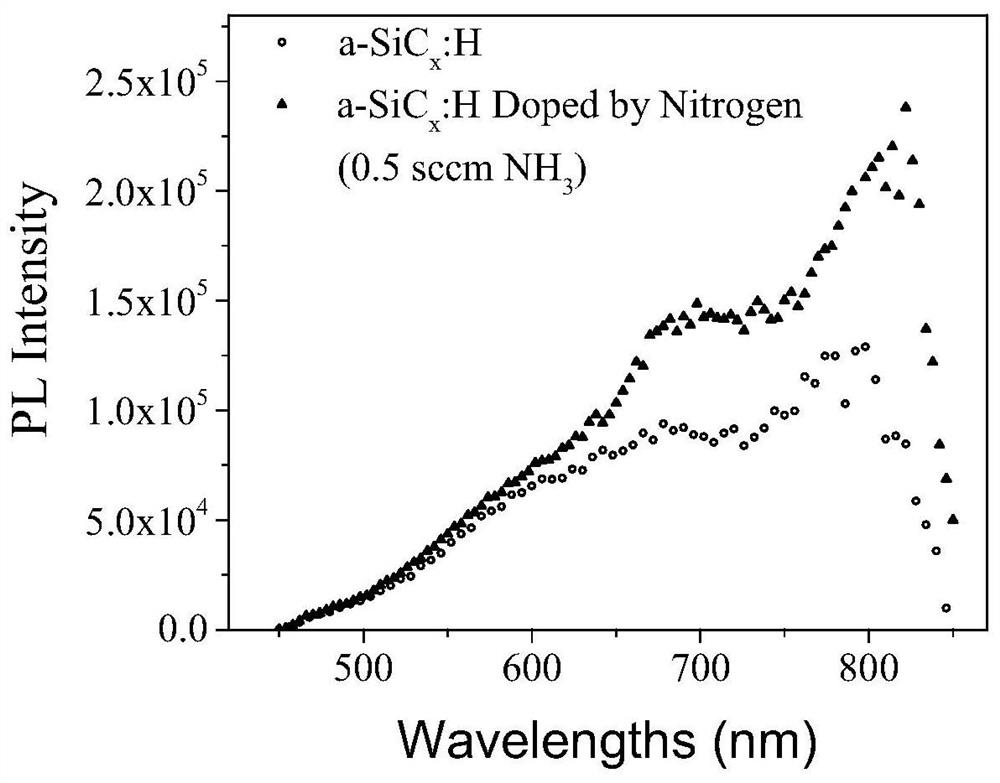
[0025] c) Ammonia gas (both with a purity of 99.9999%) is passed into the reaction chamber, and the flow rate of the ammonia gas is adjusted to 0.5 sccm, and the air extraction port of the reaction chamber is adjusted to keep the pressure of the reaction chamber at 20 Pa.
[0026] d) Apply a radio frequency signal with a radio frequency power of 30W and a radio frequency of 40.68MHz to the upper plate, control the growth time for 30 minutes, and the growth temperature at 250°C.
[0027] e) Utilize xenon lamp 350nm ultraviolet light to irradiate the thin film prepared in step d), the relationship between its photo-induced red...
Embodiment 2
[0030] a) In the flat capacitive RF plasma-enhanced chemical vapor deposition equipment, adjust the distance between the upper and lower plates of the capacitor plate to 2.5 cm, and ground the lower plate of the capacitor plate.
[0031] b) SiH 4 and CH 4 The gas is passed into the reaction chamber, SiH 4 and CH 4 The gas flow ratio is 3.5sccm:5sccm.
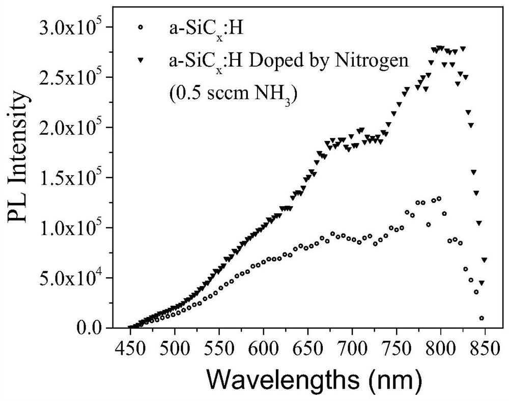
[0032] c) Ammonia gas (both with a purity of 99.9999%) is passed into the reaction chamber, and the flow rate of the ammonia gas is adjusted to 1.0 sccm, and at the same time, the air inlet of the reaction chamber is adjusted to keep the pressure of the reaction chamber at 20 Pa.
[0033] d) Apply a radio frequency signal with a radio frequency power of 30W and a radio frequency of 40.68MHz to the upper plate, control the growth time for 30 minutes, and the growth temperature at 250°C.
[0034] e) Utilize xenon lamp 350nm ultraviolet light to irradiate the thin film prepared in step d), the relationship between its photo-ind...
Embodiment 3
[0037] a) In the flat capacitive RF plasma-enhanced chemical vapor deposition equipment, adjust the distance between the upper and lower plates of the capacitor plate to 2.5 cm, and ground the lower plate of the capacitor plate.
[0038] b) SiH 4 and CH 4 The gas is passed into the reaction chamber, SiH 4 and CH 4 The gas flow ratio is 3.5sccm:5sccm.
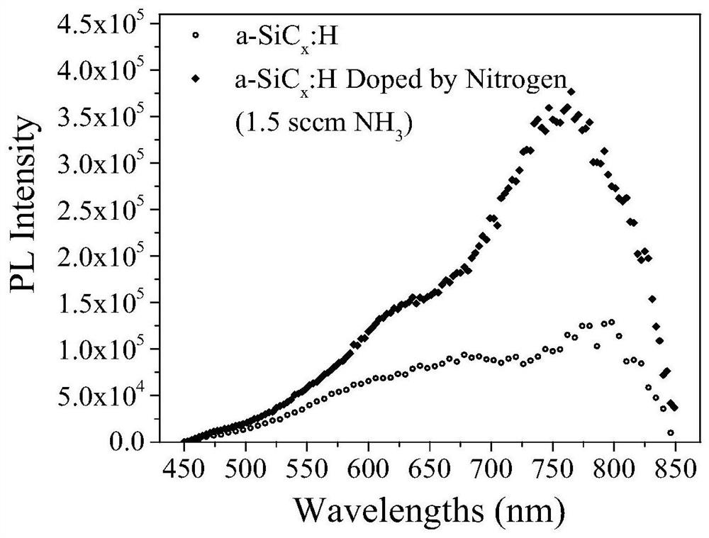
[0039] c) Ammonia gas (both with a purity of 99.9999%) is passed into the reaction chamber, and the flow rate of the ammonia gas is adjusted to 1.5 sccm, and the air inlet of the reaction chamber is adjusted to keep the pressure of the reaction chamber at 20 Pa.
[0040] d) Apply a radio frequency signal with a radio frequency power of 30W and a radio frequency of 40.68MHz to the upper plate, control the growth time for 30 minutes, and the growth temperature at 250°C.
[0041] e) Utilize xenon lamp 350nm ultraviolet light to irradiate the thin film prepared in step d), the relationship between its photo-induced red light emi...
PUM
 Abstract
Description
Claims
Application Information
 - R&D
- Intellectual Property
- Life Sciences
- Materials
- Tech Scout
- Unparalleled Data Quality
- Higher Quality Content
- 60% Fewer Hallucinations
Browse by: Latest US Patents, China's latest patents, Technical Efficacy Thesaurus, Application Domain, Technology Topic, Popular Technical Reports.
© 2025 PatSnap. All rights reserved.Legal|Privacy policy|Modern Slavery Act Transparency Statement|Sitemap|About US| Contact US: help@patsnap.com


