
MEMS pressure sensor based on frequency detection principle and preparation method thereof

A pressure sensor and principle technology, which is applied to the fluid pressure measurement using inductance changes, the fluid pressure measurement using capacitance changes, and the measurement force, etc., can solve the problems of complex preparation of piezoelectric materials, difficult standard process compatibility, and low resolution ability. , to achieve the effect of low price, improving device performance and reducing chip area

Active Publication Date: 2021-09-28
NANJING GAOHUA TECH
View PDF8 Cites 0 Cited by
  • Summary
  • Abstract
  • Description
  • Claims
  • Application Information

AI Technical Summary

Problems solved by technology

The piezoresistive pressure sensor is based on the principle of piezoresistive effect of semiconductor materials (such as polysilicon, etc.). The principle of variable quantity has high sensitivity, but poor linearity and is susceptible to interference; piezoelectric pressure sensors are based on the principle of piezoelectric effect of materials (such as PZT, AlN, etc.), and their response speed is fast, but piezoelectric materials The preparation is complicated, and some parts are difficult to be compatible with the standard process; the resonant pressure sensor is based on the principle that the resonant frequency of the structure changes with the pressure, and its sensitivity is high, but because the pressure change has little change in the frequency offset, its resolution is not high

Method used


Image

  • MEMS pressure sensor based on frequency detection principle and preparation method thereof
  • MEMS pressure sensor based on frequency detection principle and preparation method thereof
  • MEMS pressure sensor based on frequency detection principle and preparation method thereof

Examples


Embodiment Construction

[0031] The following will clearly and completely describe the technical solutions in the embodiments of the present invention with reference to the accompanying drawings in the embodiments of the present invention. Obviously, the described embodiments are only some, not all, embodiments of the present invention. Based on the embodiments of the present invention, all other embodiments obtained by those skilled in the art without creative efforts fall within the protection scope of the present invention.

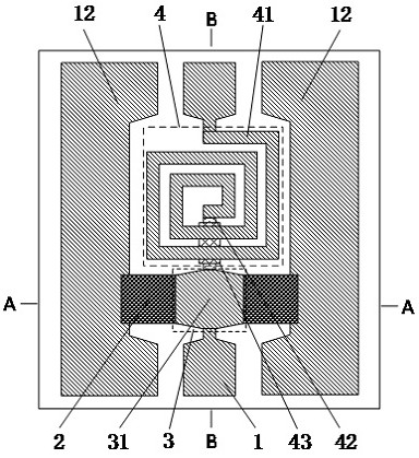
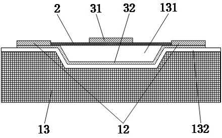
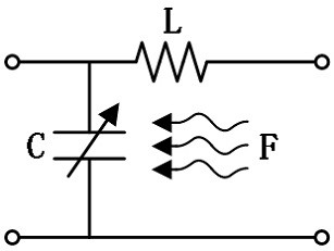
[0032] This embodiment provides a MEMS pressure sensor based on the principle of detecting frequency changes, such as Figure 1 ~ Figure 3 As shown, a buffer dielectric layer 132 , a CPW transmission line, a planar spiral inductor 4 , a MEMS variable parallel plate capacitor 3 , a MEMS thin film 2 , a groove 131 and an insulating dielectric layer 43 are arranged on the substrate 13 .

[0033] The CPW transmission line includes a CPW signal line 1 located in the middle of the s...


PUM

PropertyMeasurementUnit
depthaaaaaaaaaa
thicknessaaaaaaaaaa
electrical resistivityaaaaaaaaaa

Abstract

The invention discloses an MEMS pressure sensor based on the frequency detection principle. A planar spiral inductor is adopted, an MEMS variable parallel plate capacitor is arranged on one side of the inductor, and an LC resonance circuit is formed; the MEMS capacitor is connected in parallel between the CPW signal line and the ground wire, an upper pole plate of the MEMS capacitor is the CPW signal line and is directly arranged on the MEMS film, a groove is formed in the substrate under the MEMS film, and a lower pole plate of the MEMS capacitor is positioned on the bottom surface of the groove and two side surfaces close to the ground wire and is connected with the ground wire; the two ends of the MEMS film are arranged on the ground wire and form a closed cavity with the groove. The external pressure intensity is sensed by utilizing the closed cavity, when the internal and external pressure difference of the closed cavity is changed, the MEMS film is bent to cause the capacitance between the upper pole plate and the lower pole plate of the MEMS capacitor to change, so the resonant frequency of an RF signal on the CPW transmission line is shifted, and the magnitude of the detection pressure can be represented by measuring the resonant frequency value.

Description

technical field [0001] The invention relates to the technical field of radio frequency microelectromechanical systems (RF MEMS), in particular to a MEMS pressure sensor based on the principle of frequency detection and a preparation method. Background technique [0002] The pressure sensor can sense the pressure signal and convert the pressure signal into an easy-to-measure output electrical signal according to certain rules. It is widely used in automotive electronics, automatic control, aerospace, biomedical, environmental monitoring and other fields, and is one of the commonly used sensors in the industry. With the development of MEMS technology, pressure sensors prepared by MEMS micromachining technology have the advantages of miniaturization, low power consumption, and batch production; according to different pressure test types, pressure sensors can be divided into gauge pressure, differential pressure and absolute pressure. According to different pressure test princi...

Claims


Application Information

Patent Timeline
Patent Type & Authority Applications(China)
IPC IPC(8): G01L1/14G01L9/12G01L9/10B81B7/02B81C1/00
CPCG01L1/142G01L9/12G01L9/10B81B7/02B81C1/00134B81B2201/0264
Inventor 侯鸿道兰之康董振兴
Owner NANJING GAOHUA TECH
Learn More