
Method of hydrocarbon pyrolysis and device for implementing same

A technology of pyrolysis and raw materials, which is applied in the treatment of hydrocarbon oil, hydrocarbon oil treatment products, non-catalytic thermal cracking, etc., and can solve the problems of coke formation, high capital cost of pyrolysis furnace construction, and volume reduction of coke solid carbon particles.

Inactive Publication Date: 2021-11-05
尤里杰弗拉基米罗维奇费申科
View PDF9 Cites 0 Cited by
  • Summary
  • Abstract
  • Description
  • Claims
  • Application Information

AI Technical Summary

Problems solved by technology

[0004] However, the pyrolysis process suffers from the following disadvantages: high capital cost for the construction of the pyrolysis furnace due to the high use of high-alloy steel; limited furnace capacity due to hydraulic resistance problems in the coil piping used to heat the feedstock; Problems with coke formation; and technical difficulties in supplying large amounts of heat to coil heating elements
[0010] The disadvantage of the known method is that it is one of the embodiments of the hydrocracking process aimed at increasing the production of light petroleum products (light liquid fractions) during the pyrolysis (cracking) of heavy oil residues (fuel oils and gas oils) rate, and removal of petroleum products from sulfur by utilizing hydrogen gas (sulfur hydrotreating process)
[0015] Disadvantages of a given reactor for handling combustible carbon and / or carbonaceous products include the impossibility of obtaining any sufficient quantities of light olefins such as ethylene, propylene and butenes as pyrolysis products as they are passed through at 750-900 pyrolysis of light and middle fractions of hydrocarbons (such as gasoline and kerosene) in fractions of a second at temperatures of °C, followed by rapid cooling ("quenching") of acquired
[0017] The disadvantage of the known device is that it is a reactor for carrying out a hydrocracking process aimed at increasing the yield of light petroleum products (light liquid fractions) during the pyrolysis (cracking) of heavy oil residues (fuel oils and gas oils) Yield
However, during the operation of such a plant, the formation of coke and the volume of solid carbon particles are significantly reduced, which does not allow its use for the production of carbon black

Method used


Image

  • Method of hydrocarbon pyrolysis and device for implementing same
  • Method of hydrocarbon pyrolysis and device for implementing same
  • Method of hydrocarbon pyrolysis and device for implementing same

Examples


Embodiment 1

[0059] The proposed oxidative pyrolysis process of hydrocarbon feedstock was implemented in an oxidative pyrolysis pilot plant for processing 68 kg per hour of straight-run gasoline (boiling point IBP - 180 °C). The feedstock was heated to 500°C.

[0060] A mixture of 11% of the feedstock consumption of oxygen heated to 300°C and 8% of the feedstock consumption of steam heated to 100°C was used as the oxidizing agent. The shape of the fire-stop grille channel is square, with a side length of 8 mm and a wall thickness of 3 mm. The outflow rate of combustion products is 50 m / s, the oxidative pyrolysis reaction time is 0.003 seconds, and the length of the grid channel is 150 mm. There are 16 square grid channels in total, with 4 channels on each side of the grid.

[0061] The calculated adiabatic temperature of the reaction product is about 1100°C, and the actual temperature considering heat loss is about 950°C. Fuel oil is used as the quenching liquid. According to the calcu...

Embodiment 2

[0070] Modular combined oxidation pyrolysis device, processing 77 kg of normal pressure gas oil (boiling point 180-330 ℃) per hour. The feedstock was heated to 500°C.

[0071]A mixture of oxygen (heated to 300° C.) in an amount of 11% of the feedstock consumption and steam (heated to 100° C.) in an amount of 8% of the feedstock consumption was used as oxidizing agent. The shape of the channel of the fire-stop grid is square, with a side length of 8 mm and a wall thickness of 3 mm. The calculated flow velocity of the combustion products is 60 m / s, the oxidation pyrolysis reaction rate is 0.003 seconds, and the length of the grid channel is 150 mm. There are 16 square grate channels in total, 4 channels on each side of the grate. The calculated adiabatic temperature of the reaction product was about 1240°C, and the actual temperature considering heat loss was about 980°C. Fuel oil is used as the quenching liquid. According to the calculation, 2.0 kg of fuel oil is taken for e...

Embodiment 3

[0081] At the combined oxidative pyrolysis unit of the same model, oxidative pyrolysis of methane gas to produce hydrogen is carried out. The consumption of ethane was 19 kg / h. Heating ethane to 500°C

[0082] A mixture of 10% of the raw material consumption of oxygen (heated to 300°C) and 10% of the raw material consumption of steam (heated to 100°C) was used as the oxidizing agent. The shape of the channel of the fire-stop grid is square, the side length is 8 mm, the wall thickness is 3 mm, the calculated flow velocity of the combustion product is 60 m / s, the oxidation pyrolysis reaction rate is 0.003 seconds, and the length of the grid channel is 150 mm. There are 4 square grate channels, 2 channels on each side of the grate. The calculated adiabatic temperature of the reaction product is about 1200°C (real temperature is about 1050°C considering heat loss).

[0083] Fuel oil is used as the quenching liquid. According to the calculation, 2.2 kg of fuel oil is taken for ...


PUM

PropertyMeasurementUnit
boiling pointaaaaaaaaaa
densityaaaaaaaaaa
densityaaaaaaaaaa

Abstract

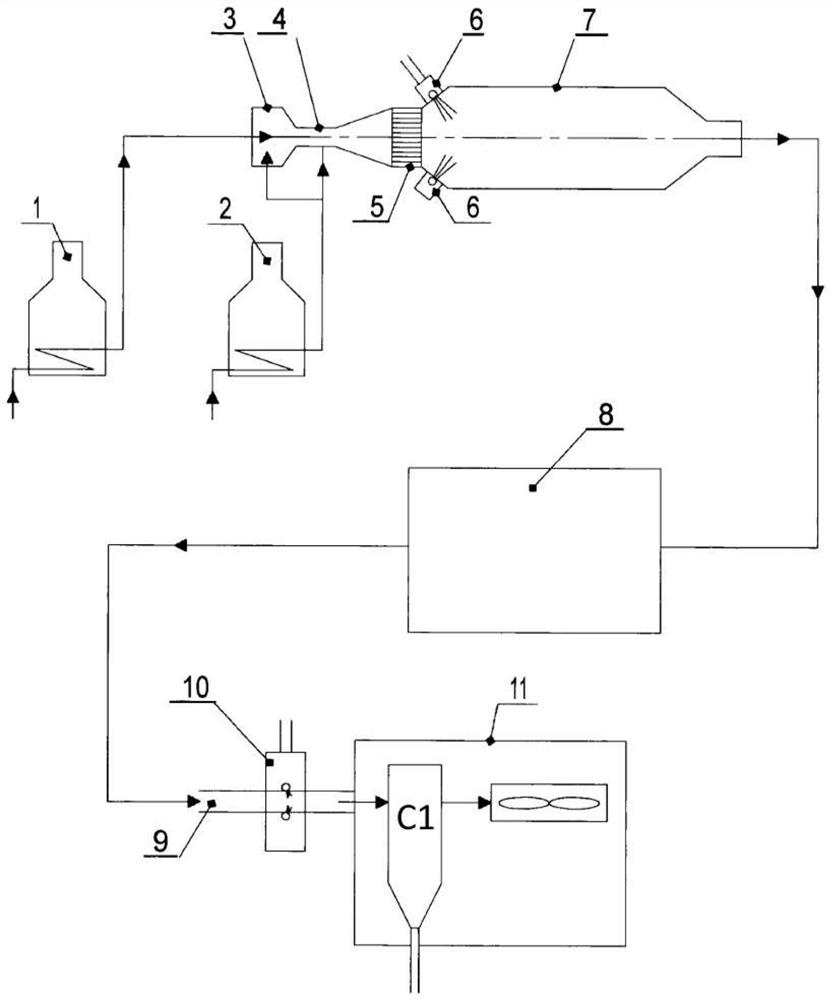
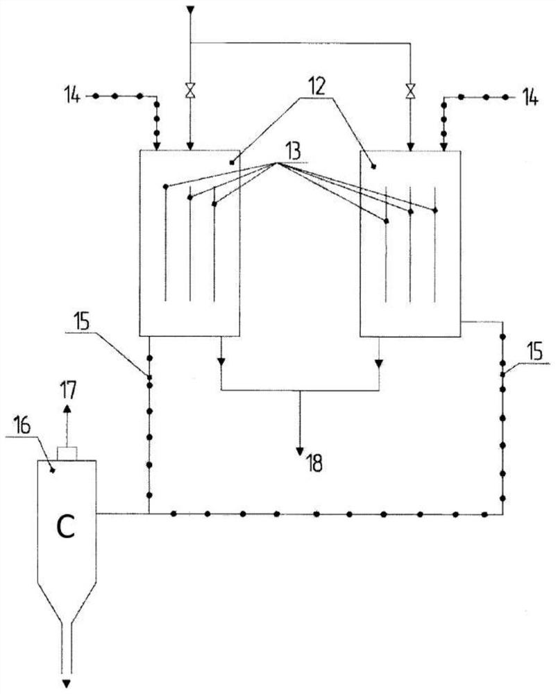
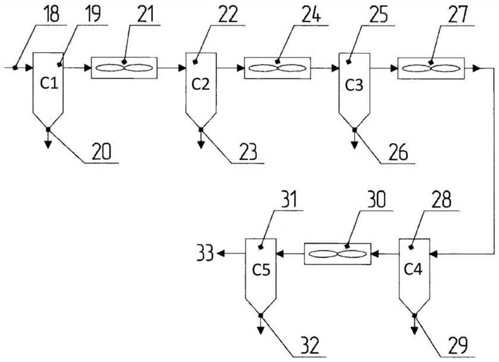
The invention relates to oxidative pyrolysis of hydrocarbon feedstock. A method of oxidative pyrolysis comprises heating hydrocarbon feedstock, heating a steam-oxygen mixture, combusting the hydrocarbon feedstock in vapors of the steam-oxygen mixture in a special reactor, rapidly cooling the resulting incomplete combustion products of the chemical reactions in two steps, and then sending the cooled steam-gas mixture into a fractionation unit. A device for hydrocarbon pyrolysis comprises a chamber for mixing the steam-oxygen mixture and the feedstock, a pyrolysis chamber and a coking reactor, a device for heating the hydrocarbon feedstock and a device for heating the steam-oxygen mixture which are connected to the mixing chamber, a coking reactor supplied with a device for feeding cooling liquid into the pyrolysis gas stream, a separation unit connected to the coking reactor, and a fractionation unit equipped with an additional device for feeding cooling liquid. The technical result is highly cost-effective and environmentally friendly recovery of heavy petroleum residues by rapid coking that produces a high-quality coke, and the production of aromatic compounds without the construction or use of separate specialized installations.

Description

technical field [0001] The invention belongs to the oxidative pyrolysis and rapid coking of hydrocarbon raw materials, especially gasoline fraction, kerosene, gas oil, ethane, propane and butane, and can be used in petrochemical industry. Background technique [0002] Currently, the petrochemical industry consumes large quantities of pyrolysis products (thermal, oxidized) of petroleum fractions (gasoline, kerosene, gas oil) used for the production of plastics, synthetic yarns, rubber, etc. Meanwhile, pyrolysis products such as light olefins, especially ethylene and propylene, are the most valuable (30% to 45% by mass of pyrolysis product) [1, p. 54]. In addition, pyrolysis by-products such as aromatics are also in great demand (benzene, toluene, xylenes, naphthalene account for 8% to 15% of pyrolysis product mass) [1, pp. 54-56]. At the same time, there is an urgent need to improve refinery processing efficiencies, including the production of petroleum coke as an end produc...

Claims


Application Information

Patent Timeline
Patent Type & Authority Applications(China)
IPC IPC(8): C10G9/38B01J19/26C10B55/00
CPCC10B55/00C10G9/38C10G2300/1037C10G2400/20C10G2400/30C01B32/05B01J6/008B01J4/001B01J19/2425B01J2219/00123B01J2219/00051B01J2219/00159B01J4/002B01J19/26
Inventor 尤里杰·弗拉基米罗维奇·费申科
Owner 尤里杰弗拉基米罗维奇费申科
Learn More