
Method and device for obtaining CO2 from oil production well outlet in carbon dioxide oil recovery method

A technology for carbon dioxide and oil production wells, applied in chemical instruments and methods, separation methods, inorganic chemistry, etc., can solve problems affecting the utilization process of methane and other gases, hydrogen sulfide corrosion equipment and pipelines, environmental pollution, etc., to achieve easy toxicity, Ensure safe mining and high selectivity

Active Publication Date: 2022-01-11
DESHI ENERGY TECH GRP CO LTD
View PDF0 Cites 0 Cited by
  • Summary
  • Abstract
  • Description
  • Claims
  • Application Information

AI Technical Summary

Problems solved by technology

[0003] At present, the concentration of carbon dioxide in the associated gas is relatively high, and it also contains a certain amount of methane, heavy hydrocarbons, nitrogen, and hydrogen sulfide gas. The carbon dioxide in the associated gas is recovered by means of absorption separation, membrane separation, adsorption separation, and low-temperature condensation. However, the above-mentioned Method The recovered carbon dioxide often contains a certain amount of hydrogen sulfide. If hydrogen sulfide cannot be removed from carbon dioxide, hydrogen sulfide will corrode equipment and pipelines during the recovery of carbon dioxide, and hydrogen sulfide will exist in methane and other gases. Affect the subsequent utilization process of methane and other gases, causing pollution to the environment

Method used


Image

  • Method and device for obtaining CO2 from oil production well outlet in carbon dioxide oil recovery method
  • Method and device for obtaining CO2 from oil production well outlet in carbon dioxide oil recovery method
  • Method and device for obtaining CO2 from oil production well outlet in carbon dioxide oil recovery method

Examples


Embodiment 1

[0054] This embodiment relates to a preparation method of an additive, and the preparation method comprises the following steps:

[0055] S1: Dissolve N-hydroxyethyl-N-methylbenzylamine, p-carboxystyrene acid and 2-acetamidoacrylic acid at a weight ratio of (10-30):(3-8):1 in the solvent, and stir Evenly, add concentrated sulfuric acid, heat up to 80-150°C, and react for 2-5 hours to obtain an intermediate solution;

[0056] S2: Lower the temperature of the intermediate solution to 40-120°C, add N,N-methylenebisacrylamide and catalyst to the intermediate solution and polymerize for at least 8 hours under nitrogen, and obtain the additive after purification and drying, where N, The weight ratio of N-methylenebisacrylamide to N-hydroxyethyl-N-methylbenzylamine is (2-10):(5-20).

[0057] Preferably, step S2, adding nano-montmorillonite to the intermediate solution, stirring at 80-150°C for more than 1 hour, then adding N,N-methylenebisacrylamide, catalyst and silica sol, stirrin...

Embodiment 2

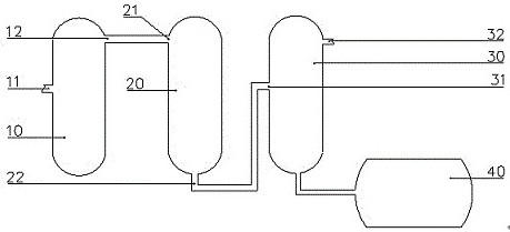
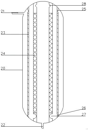
[0103] This embodiment relates to a device for obtaining carbon dioxide from the outlet of an oil well, the device comprising a first recovery tower 10, the first recovery tower 10 is provided with a first air inlet 11 and a first gas outlet 12, and the first recovery tower 10 is connected with The first compressor, and the first recovery tower 10 is externally connected with the first refrigeration mechanism; the second recovery tower 20, the second recovery tower 20 is provided with a second air inlet 21 and a second gas outlet 22, and in the second recovery tower 20 The impurity removal channel is set, and the impurity removal channel is used to place the additive; the third recovery tower 30, the third recovery tower 30 is provided with the third air inlet 31 and the third gas outlet 32, and the third recovery tower 30 is connected with the second compressor and Second refrigeration mechanism.

[0104] The associated gas passes through the first recovery tower 10, and the ...

Embodiment 3

[0108] This example relates to a method for obtaining carbon dioxide from the outlet of the oil production well. This example uses the additive 1# in Example 1 and the device in Example 2 to recover the associated gas obtained from the outlet of the oil production well. Oil wells use liquid carbon dioxide to drive oil, so the concentration of carbon dioxide in the associated gas is relatively high. The specific recovery methods are as follows:

[0109] (1) Collect associated gas from the outlet of the oil production well, lower the temperature of the associated gas to 10-20°C, and pressurize the associated gas to 2.5-4.0MPa, so as to conduct preliminary treatment of the associated gas to obtain the first treated gas;

[0110] (2) Contact the first treatment gas with additives to remove hydrogen sulfide in the first treatment gas, the removal temperature is 100°C to obtain the second treatment gas, and lower the temperature of the second treatment gas to 32-40°C , the pressure ...


PUM

PropertyMeasurementUnit
pore sizeaaaaaaaaaa
pore sizeaaaaaaaaaa

Abstract

This application discloses a carbon dioxide oil recovery method to obtain CO from the outlet of the oil production well 2 The method and device belong to the field of carbon dioxide recovery and utilization. The method includes the following steps: (1) collecting associated gas from the outlet of the oil production well, and pressurizing the associated gas, so as to perform preliminary treatment on the associated gas to separate water and heavy hydrocarbons, and obtain the first treated gas; (2) Contact the first treatment gas with an additive to remove hydrogen sulfide in the first treatment gas to obtain a second treatment gas, and pressurize and cool the second treatment gas to obtain liquid carbon dioxide ; The raw materials for the preparation of the additive include N-hydroxyethyl-N-methylbenzylamine, p-carboxystyrene acid, 2-acetamidopropene and N,N-methylenebisacrylamide. The additive is used to selectively adsorb the hydrogen sulfide gas in the first treatment gas, which can reduce the hydrogen sulfide content in the liquid carbon dioxide and improve the purity of the recovered carbon dioxide.

Description

technical field [0001] The present application relates to obtaining CO from the outlet of the production well in a carbon dioxide oil recovery method 2 The method and device belong to the field of carbon dioxide recovery and utilization. Background technique [0002] Carbon dioxide flooding technology can not only increase the recovery rate of crude oil and reduce the viscosity of crude oil, but also can store carbon dioxide underground and reduce the content of carbon dioxide in the atmosphere. However, in the process of oil extraction, a part of the injected carbon dioxide gas will form associated gas with the production of crude oil. The associated gas contains a relatively high concentration of carbon dioxide, and direct emission will cause air pollution. It can reduce the cost of carbon dioxide flooding and protect the ecological environment. [0003] At present, the concentration of carbon dioxide in the associated gas is relatively high, and it also contains a certa...

Claims


Application Information

Patent Timeline
Patent Type & Authority Patents(China)
IPC IPC(8): B01D53/04B01J20/26C01B32/50E21B43/34
CPCB01D53/04B01J20/261E21B43/34C01B32/50B01D2257/304Y02P20/151
Inventor 崔仕章侯云福宋新旺王黎明张凤莲张荣军曾刚
Owner DESHI ENERGY TECH GRP CO LTD
Learn More