Incineration system for treating sulfur-containing, nitrogen-containing and salt-containing waste liquid

A technology for salt-containing waste liquid and waste liquid, applied in the field of incineration system, which can solve the problems of corrosion, blockage of flue gas channels, and increased investment.

Pending Publication Date: 2021-12-31
上海瑞鼎环境工程技术有限公司 +1
View PDF0 Cites 2 Cited by
  • Summary
  • Abstract
  • Description
  • Claims
  • Application Information

AI Technical Summary

Problems solved by technology

[0003] This method has the following disadvantages: (1) In order to prevent the molten inorganic salts and ash in the high-temperature flue gas from solidifying and sticking to the surface of the heat exchange tube, affecting the heat exchange efficiency and gradually accumulating to block the flue gas passage, Before the flue gas enters the waste heat boiler, it adopts the cooling measures of blowing cold air
A large amount of cold air will be discharged into the atmosphere in the form of smoke exhaust, resulting in low efficiency of waste heat recovery. In addition, the amount of flue gas is increased, and the model size of downstream equipment is also increased, which increases investment.
(2) The technology injects NH into the SNCR section 3 Easy to interact with SO in flue gas 2 , SO 3 The re...

Method used


Image

  • Incineration system for treating sulfur-containing, nitrogen-containing and salt-containing waste liquid

Examples


Embodiment Construction

[0030] The following will clearly and completely describe the technical solutions in the embodiments of the application with reference to the drawings in the embodiments of the application. Apparently, the described embodiments are only some of the embodiments of the application, not all of them. Based on the embodiments in this application, all other embodiments obtained by persons of ordinary skill in the art without making creative efforts belong to the scope of protection of this application.

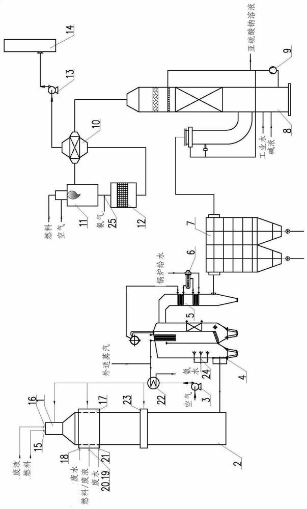
[0031] Such as figure 1 As shown, in one of the embodiments of the present application, an incineration system for treating sulfur-containing, nitrogen-containing, and salt-containing waste liquids includes:

[0032] The incinerator 2 is provided with a waste liquid delivery pipeline and a fuel delivery pipeline;

[0033] The waste heat boiler 4, the high-temperature flue gas generated after being incinerated by the incinerator 2 enters the waste heat boiler 4 from the outlet of th...


PUM


Abstract

The invention discloses an incineration system for treating sulfur-containing, nitrogen-containing and salt-containing waste liquid. The system comprises an incinerator, a waste heat boiler, an economizer, a desulfurization tower and a denitration device, and the incinerator is provided with a waste liquid conveying pipeline and a fuel conveying pipeline; high-temperature flue gas generated after incineration of the incinerator enters the waste heat boiler from an outlet of the incinerator; the economizer is connected with the waste heat boiler, and after high-temperature flue gas treated by the waste heat boiler enters the economizer from an outlet of the waste heat boiler, heat continues to be recycled; the high-temperature flue gas treated by the coal economizer enters the desulfurization tower to be subjected to desulfurization treatment; and the high-temperature flue gas treated by the desulfurization tower enters the denitration device for denitration treatment. According to the invention, a process technical route of staged combustion-waste heat recovery-first desulfurization and then denitration is adopted, and toxic and harmful substances are oxidized and decomposed through high-temperature incineration; and by adopting the mode that the flue gas is desulfurized, heated and then denitrated, the blockage and corrosion of ammonium bisulfite and ammonium bisulfate to downstream equipment such as the coal economizer are avoided, and the environment-friendly emission requirement of NOx is met.

Description

technical field [0001] The application belongs to the technical field of waste liquid treatment, and in particular relates to an incineration system for treating waste liquid containing sulfur, nitrogen and salt. Background technique [0002] Usually sulfur-containing, nitrogen-containing, and salt-containing waste liquid treatment devices are used for toxic, harmful, and refractory wastes containing acrylonitrile, acetonitrile, hydrocyanic acid, acrolein, acetaldehyde, propionitrile, polymers, ammonium sulfate, and sodium salts. substance. Domestic related devices mainly use incineration to treat this kind of wastewater. The common incineration method is to use auxiliary fuel to incinerate toxic organic substances in wastewater at high temperature. The lower part of the incinerator is equipped with a SNCR (Selective Non-Catalytic Reduction, Selective Non-Catalytic Reduction) denitrification section, and the outlet of the incinerator is connected to the waste heat recovery ...

Claims


Application Information

Patent Timeline
IPC IPC(8): F23G5/08F23G5/44F23G5/46F23G7/04F23J15/02
CPCF23G7/04F23G5/08F23G5/44F23G5/46F23J15/02F23J15/025F23J2215/20
Inventor 王尚文孟祥龙张树宝路遥郑军如陈敏东
Owner 上海瑞鼎环境工程技术有限公司
Why Eureka
Try Eureka