Large-mode-field single-mode radiation-resistant erbium-ytterbium co-doped optical fiber and preparation method thereof

A radiation-resistant, large-mode-field technology, applied in cladding optical fiber, glass manufacturing equipment, glass fiber products, etc., can solve the problems of performance degradation and failure of erbium-ytterbium co-doped optical fiber, and improve the stability of radiation-resistant reinforcement , large mode field area, and the effect of reducing the refractive index

Active Publication Date: 2022-01-11
XI'AN INST OF OPTICS & FINE MECHANICS - CHINESE ACAD OF SCI
View PDF5 Cites 1 Cited by
  • Summary
  • Abstract
  • Description
  • Claims
  • Application Information

AI Technical Summary

Problems solved by technology

[0006] In order to solve the problem of performance degradation or even failure of erbium-ytterbium co-doped fiber under high-energy particle irradiation conditions and

Method used


Image

  • Large-mode-field single-mode radiation-resistant erbium-ytterbium co-doped optical fiber and preparation method thereof
  • Large-mode-field single-mode radiation-resistant erbium-ytterbium co-doped optical fiber and preparation method thereof
  • Large-mode-field single-mode radiation-resistant erbium-ytterbium co-doped optical fiber and preparation method thereof

Examples


preparation example Construction

[0046] The preparation method of the large-mode-field single-mode radiation-resistant erbium-ytterbium co-doped optical fiber comprises the following steps:

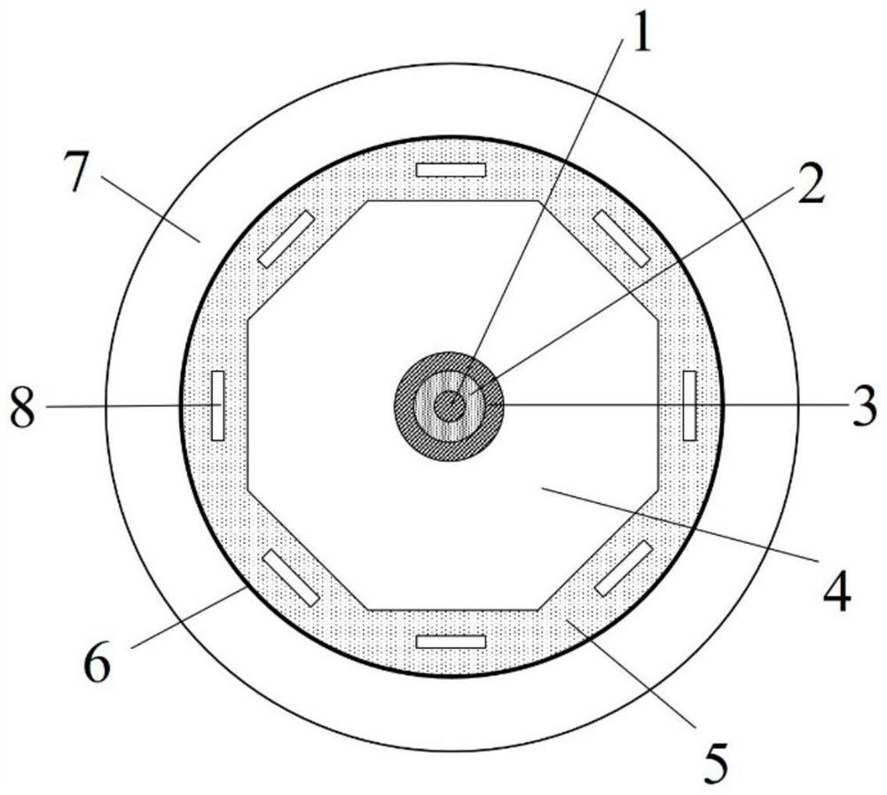
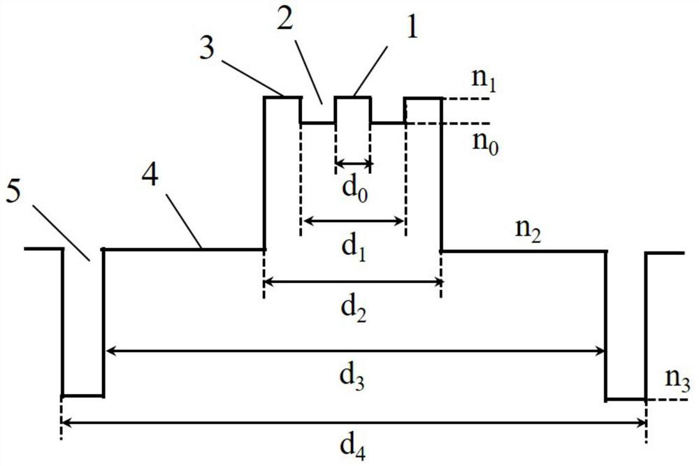
[0047] Step 1), using a quartz tube as a deposition liner, wherein the thickness of the quartz deposition tube is 0.5-1.0mm, using MCVD combined with chelate vapor deposition method to prepare the fiber core, after preheating and impurity removal treatment, according to the flow rate of the core components Design and set the flow rate of reaction materials and oxygen. The deposition temperature is 1600-1900°C. The ring outer core layer 3, the annular sunken core layer 2, and the center core layer 1 are deposited in sequence, and a solid core rod is shrunk by a single shrinkage process. Among them, the hydrogen flow rate is 90-120 sccm;

[0048] Step 2), according to the requirements of the fiber core cladding ratio, use the casing process to coat the quartz tube on the core rod, form the inner cladding 4 on the outer lay...

Embodiment

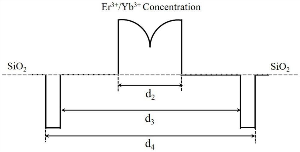
[0060] The preparation method of the erbium-ytterbium co-doped optical fiber preform is the same as the comparative example, the deposition liner adopts a 28 / 26mm quartz tube (28mm is the outer diameter of the quartz deposition tube, and 26mm is the inner diameter of the quartz deposition tube), and the reaction materials are respectively SiCl 4 、Er(TMHD) 3 、Yb(TMHD) 3 、Ce(TMHD) 3 , POCl 3 、SiF 4 etc., the specific flow rate is shown in Table 2, and the ring outer core layer 3, the ring sunken core layer 2, and the center core layer 1 were deposited in sequence, and the deposition temperature was 1850°C. After the deposition, the quartz tube is shrunk into a solid rod by using a single shrinkage process with a hydrogen flow rate of 90-120 sccm. The difference is that an outer cladding layer 5 is added to the outer layer of the preform in the comparative example, and the outer cladding layer 5 is a sunken fluorine-doped layer, which is prepared by plasma chemical vapor depo...


PUM


Abstract

The invention discloses a large-mode-field single-mode radiation-resistant erbium-ytterbium co-doped optical fiber and a preparation method thereof, and solves the problems of performance reduction or even failure and higher-power single-mode output of an erbium-ytterbium co-doped optical fiber under the existing high-energy particle radiation condition, and the large-mode-field single-mode radiation-resistant erbium-ytterbium co-doped optical fiber comprises a fiber core, an inner cladding and an outer cladding which are sequentially arranged from inside to outside; the fiber core comprises a central core layer, an annular sunken core layer and an annular outer core layer which are sequentially arranged from inside to outside; the contents of Er and Yb components of the fiber core are distributed in a power function gradual change manner along the radial direction from inside to outside, the index alpha of the power function is 0.3-0.6, and the specific contents are as follows: 0.05-0.3 Wt.% of Er and 1-5Wt.% of Yb; the fiber core co-doped components are P, Ce and F; and the outer cladding layer is a sunken fluorine-doped layer.

Description

technical field [0001] The invention belongs to the field of optical fiber technology, and in particular relates to a large-mode-field single-mode radiation-resistant erbium-ytterbium co-doped optical fiber and a preparation method thereof. Background technique [0002] Space laser communication technology has the advantages of fast transmission rate, large communication capacity, strong anti-electromagnetic interference performance, and high confidentiality, and its communication terminal is small in size, low in power consumption, and extremely practical. It is considered to solve the problem of insufficient bandwidth of traditional radio communication, The best solution with low speed and poor real-time performance. As a key component of the space laser communication system, the fiber amplifier is mainly used for high-power amplification of the optical transmitting system and preamplification of the optical receiving system, and plays an important role in the space laser ...

Claims


Application Information

Patent Timeline
IPC IPC(8): G02B6/036G02B6/02C03B37/018C03B37/027C03C25/54C03C25/44C03C25/26C03C25/1065
CPCG02B6/036G02B6/02009G02B6/03661C03B37/018C03B37/01853C03C25/54C03C25/44C03C25/26C03C25/109C03B2203/24C03B2203/32
Inventor 折胜飞侯超奇郭海涛高崧张岩李艺昭王根成
Owner XI'AN INST OF OPTICS & FINE MECHANICS - CHINESE ACAD OF SCI
Why Eureka
Try Eureka