Micromechanical resonator and preparation method thereof
A micromechanical resonator and resonator technology, applied in the field of microelectronics, can solve problems such as energy loss, achieve the effect of improving Q value and reducing anchor point loss
- Summary
- Abstract
- Description
- Claims
- Application Information
AI Technical Summary
Problems solved by technology
Method used
Image

Examples
preparation example Construction
[0067] In the second aspect, the present invention provides a method for preparing a micromechanical resonator. The connecting part of the support beam and the resonator is made by photolithography using a laser direct writing process or a thermal reflow process, or using a laser or ion beam without masking It is manufactured by film etching; the above-mentioned micro-mechanical resonator is prepared by adopting the preparation method of the micro-mechanical resonator.
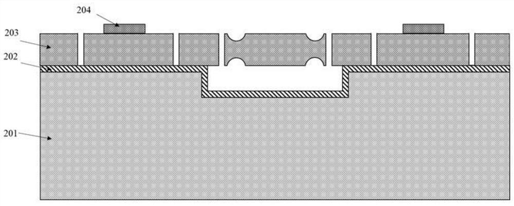
[0068] (1) The prepared micromechanical resonator is a capacitive resonator, and the preparation method comprises the following steps:
[0069] Step 1, etching a cavity structure on the substrate silicon wafer, and growing a buried oxide layer on the surface of the substrate silicon wafer;
[0070] Step 2, photoetching and patterning the lower surface of the device layer silicon to form a structure in which the size of the lower surface of the device layer silicon varies in the thickness direction;
[0071] S...
Embodiment 1
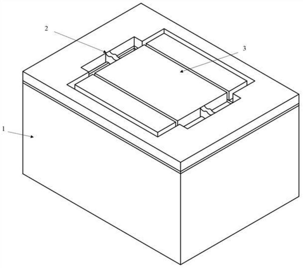
[0101] figure 1 It is shown that the resonant oscillator provided by Embodiment 1 is a capacitive resonator with a thin film structure of single crystal silicon.
[0102] Specifically, a micromechanical resonator includes a substrate silicon chip 1 and a resonator structure, the front side of the substrate silicon chip 1 is provided with a cavity structure; the resonator structure includes a resonant oscillator 3 and a support beam 2 .
[0103] The resonant oscillator 3 is suspended above the cavity structure, and the resonant oscillator 3 is connected to the silicon substrate 1 through the support beam 2 .
[0104] The support beam 2 is located at the boundary of the resonant oscillator 3, and the thickness direction of the connection between the support beam 2 and the resonant oscillator 3 is gradual, specifically, the upper and lower surfaces of the support beam 2 have a concave geometry. structure.
[0105] The cross-section of the support beam 2 is a Boolean subtraction...
Embodiment 2
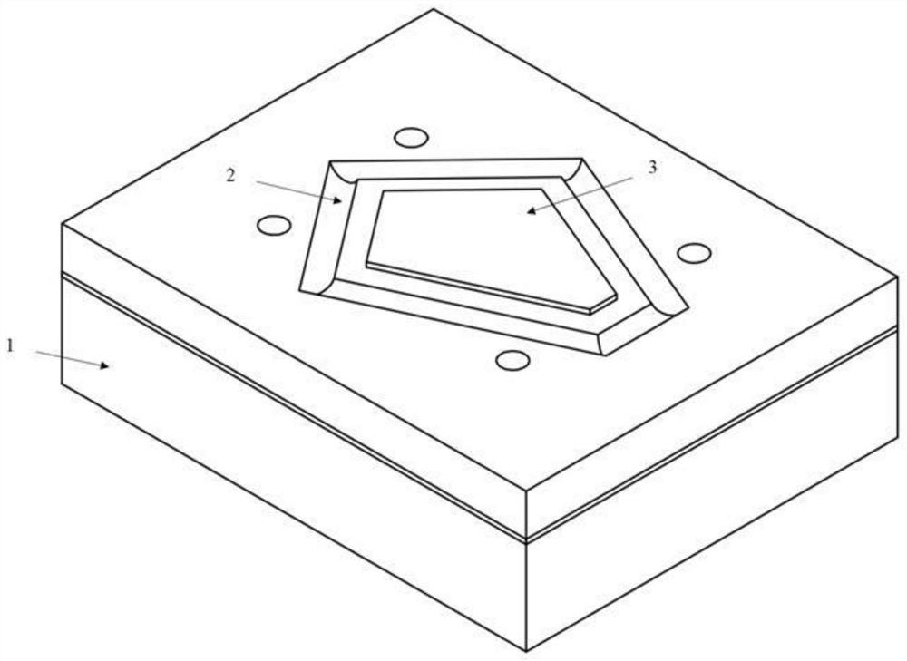
[0114] image 3 It is shown that the resonant vibrator provided in Embodiment 2 is a piezoelectric resonator with a metal-piezoelectric layer-metal composite film structure.
[0115] The difference from the first embodiment is that the resonant oscillator 3 in the first embodiment is a single structure including single crystal silicon, the resonant oscillator 3 is a rectangular plate, and the micromechanical resonator is a capacitive resonator. In Embodiment 2, the resonant vibrator 3 is a composite film structure including metal-piezoelectric layer-metal, the resonant vibrator 3 is a polygonal plate, the support beam 2 is located at the vibration node, the number of support beams 2 is multiple, and the resonance Vibrator 3 is connected to substrate silicon chip 1 through support beam 2; the micromechanical resonator is a piezoelectric resonator, and the material of the piezoelectric layer is quartz, aluminum nitride, scandium-doped aluminum nitride, zinc oxide , any one of l...
PUM
 Abstract
Description
Claims
Application Information
 - R&D
- Intellectual Property
- Life Sciences
- Materials
- Tech Scout
- Unparalleled Data Quality
- Higher Quality Content
- 60% Fewer Hallucinations
Browse by: Latest US Patents, China's latest patents, Technical Efficacy Thesaurus, Application Domain, Technology Topic, Popular Technical Reports.
© 2025 PatSnap. All rights reserved.Legal|Privacy policy|Modern Slavery Act Transparency Statement|Sitemap|About US| Contact US: help@patsnap.com