Cathode material coated with co-embedded film, preparation method and lithium ion battery

A cathode material and coating technology, which is applied in the field of battery materials, can solve problems such as difficult deposition of three-dimensional powder particles, uneven powder coating, and affecting the conductivity of materials, so as to achieve high capacity and cycle performance, block electrolyte erosion, reduce The effect of modified costs

Active Publication Date: 2022-03-08
XIAMEN YUNMAO TECH CO LTD
View PDF12 Cites 1 Cited by
  • Summary
  • Abstract
  • Description
  • Claims
  • Application Information

AI Technical Summary

Problems solved by technology

This method involves solid-liquid separation in actual production, which consumes a lot of energy, and it is difficult to control the thickness uniformity of the coating material by the solution method. Since silicon dioxide itself is not conductive, too thick coating will affect the conductivity of the material
[0004] In addition, Chinese patent CN110492067A discloses a method for preparing an aluminum-titanium composite coated nickel-cobalt-manganese positive electrode material. The method adopts a vapor deposition method for coating. This chemical deposition method controls the coating amount completely by controlling the reaction time, so It is difficult to precisely control the thickness of the cladding layer, not only the utilization rate of the reactant is not high due to too much passing through, but also it is difficult to deposit three-dimensional powder particles by chemical vapor deposition, and it is even more difficult to achieve uniform deposition in the accumulated powder
Therefore, chemical vapor deposition not only consumes a lot, and the powder coating is uneven, but also introduces a large amount of inactive substances if the coating is too thick, thereby further reducing the capacity of the positive electrode material.

Method used


Image

  • Cathode material coated with co-embedded film, preparation method and lithium ion battery
  • Cathode material coated with co-embedded film, preparation method and lithium ion battery
  • Cathode material coated with co-embedded film, preparation method and lithium ion battery

Examples

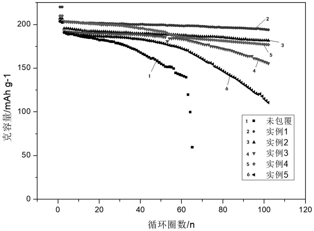
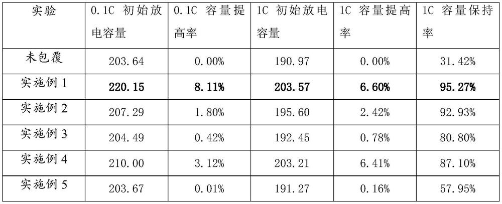

preparation example Construction

[0035] The present invention also provides a method for preparing a positive electrode material coated with a co-embedded film, comprising the following steps:

[0036] S1. Put the positive electrode material into the reaction chamber of the atomic layer deposition equipment, set the pressure of the reaction chamber to 0.001-1.0 tor, and the temperature to 25-400° C. and keep it for 1-5 hours;

[0037] S2. Feed precursor A into the reaction chamber, the feed time is 0.01-10s, the reaction time is 1-30s, the reaction times is 1-10 times, and then purge gas is fed to purge excess precursor Body A and by-products;

[0038] S3, feed precursor B into the reaction chamber, the feed time is 0.01-10s, the reaction time is 1-30s, the reaction times is 1-10 times, and then feed the cleaning gas to purge the excess precursor Body B and by-products;

[0039] S4. Steps S2 and S3 are repeated, and the number of repetitions is 0 to 4 times;

[0040] S5. Feed precursor C into the reaction ...

Embodiment 1

[0049] This embodiment provides a positive electrode material coated with a co-embedded film, which is prepared according to the following method:

[0050] (1) Weigh 10 g of the high-nickel ternary material 811 and put it into the reaction chamber of the atomic layer deposition equipment, evacuate to 0.01 torr, set the reaction temperature to 250° C., and hold the time to 2.0 h.

[0051] (2) Use trimethyl phosphate as precursor A, heat the source bottle to 75-85°C, and feed trimethyl phosphate into the reaction chamber for 2 s, 10 s, and 1 reaction time.

[0052] (3) Introduce Ar gas to purge excess trimethyl phosphate and by-products, the purge time is 60s, and the purge times are 2 times.

[0053] (4) with H 2 O is used as the precursor B, and H is introduced into the reaction chamber 2 O, the access time is 1s, the reaction time is 5s, and the number of reactions is 1 time.

[0054] (5) Introduce Ar gas to purge excess H 2 O and by-products, the purging time is 60s, and...

Embodiment 2

[0063] In this embodiment, a positive electrode material coated with a co-embedded film is provided, which is prepared according to the following method:

[0064] (1) Weigh 10 g of the high-nickel ternary material 811 and put it into the reaction chamber of the atomic layer deposition equipment, evacuate to 0.01 torr, set the reaction temperature to 250° C., and hold the time to 2.0 h.

[0065] (2) Use trimethyl phosphate as precursor A, heat the source bottle to 75-85°C, and feed trimethyl phosphate into the reaction chamber for 2 s, 10 s, and 1 reaction time.

[0066] (3) Introduce Ar gas to purge excess trimethyl phosphate and by-products, the purge time is 60s, and the purge times are 2 times.

[0067] (4) with H 2 O is used as the precursor B, and H is introduced into the reaction chamber 2 O, the access time is 1s, the reaction time is 5s, and the number of reactions is 1 time.

[0068] (5) Introduce Ar gas to purge excess H 2 O and by-products, the purging time is 6...


PUM


Abstract

According to the positive electrode material coated with the co-embedded thin film, the preparation method and the lithium ion battery, the co-embedded thin film is deposited on the surface of the positive electrode material through an atomic layer deposition method, so that the positive electrode material coated with the co-embedded thin film is obtained. The co-embedded thin film comprises an amorphous oxide layer of phosphorus and an amorphous oxide layer of titanium. By adopting the atomic layer deposition method, the precise regulation and control of the element content and proportion can be realized, the cost is low, the coating period is short, and the PO bond in the obtained co-embedded film with the specific element proportion and content can prevent the material structure collapse caused by material deoxidation; and the amorphous oxide layer of phosphorus and residual lithium of the positive electrode material can form fast ion conductor lithium phosphate, so that the interface impedance is reduced. The amorphous oxide layer of titanium has the effect of blocking electrolyte erosion. Therefore, the positive electrode material coated with the co-embedded film and the lithium ion battery assembled by the positive electrode material have relatively high capacity and cycle performance.

Description

technical field [0001] The invention relates to the technical field of battery materials, and in particular to a positive electrode material coated with a co-embedded thin film, a preparation method and a lithium ion battery. Background technique [0002] Lithium-ion batteries play an important role in energy storage and conversion. With the development of new energy vehicles and the increase in demand for power batteries, my country's lithium battery shipments are also increasing year by year. While the demand for lithium batteries is increasing, people are most concerned about the safety, cycle stability, energy density and cost of lithium batteries. In lithium batteries, the cost of cathode materials accounts for 40% of the cost of the entire battery and determines 60% of the performance of the entire lithium battery. Therefore, improving the cycle life of cathode materials, increasing energy density, reducing impedance and reducing production costs will be urgent probl...

Claims


Application Information

Patent Timeline
Patent Type & Authority Applications(China)
IPC IPC(8): H01M4/62H01M4/36H01M4/505H01M4/525H01M4/04H01M10/0525C23C16/40C23C16/455
CPCH01M4/366H01M4/505H01M4/525H01M4/624H01M4/628H01M4/0428H01M10/0525C23C16/45527C23C16/40C23C16/405H01M2004/021H01M2004/028Y02E60/10
Inventor 陈斌王韫宇
Owner XIAMEN YUNMAO TECH CO LTD
Why Eureka
Try Eureka