Composite coating, preparation method thereof and thermal barrier coating

A composite coating and thermal barrier coating technology, which is applied in the coating, metal material coating process, vacuum evaporation coating, etc., can solve the problems of inability to completely remove the thermal barrier coating surface, slow reaction rate, poor high temperature stability, etc. question

Active Publication Date: 2022-03-25
BEIHANG UNIV
View PDF6 Cites 0 Cited by
  • Summary
  • Abstract
  • Description
  • Claims
  • Application Information

AI Technical Summary

Problems solved by technology

As the service temperature and life of aero-engines continue to increase, one of the main chemical components is CaO-MgO-Al2O3-SiO2 (referred to as CMAS) environmental deposits are increasingly harmful to the thermal barrier coating of engine blades. On the one hand, it leads to the blockage of air film cooling holes on the surface of the blade and reduces the cooling effect; on the other hand, it causes a significant decrease in the service life of TBCs of the blade
[0003]At present, the surface modification of thermal barrier coatings to prevent CMAS corrosion is mainly divided into two aspects: one is to use physical isolation to prepare a An inert, dense coating (such as alumina, etc.) prevents CMAS from penetr

Method used


Image

  • Composite coating, preparation method thereof and thermal barrier coating
  • Composite coating, preparation method thereof and thermal barrier coating
  • Composite coating, preparation method thereof and thermal barrier coating

Examples


preparation example Construction

[0049] In some embodiments, the method for preparing the thermal barrier coating can be any known method for preparing a coating. In a specific embodiment, the preparation method of thermal barrier coating comprises the following steps:

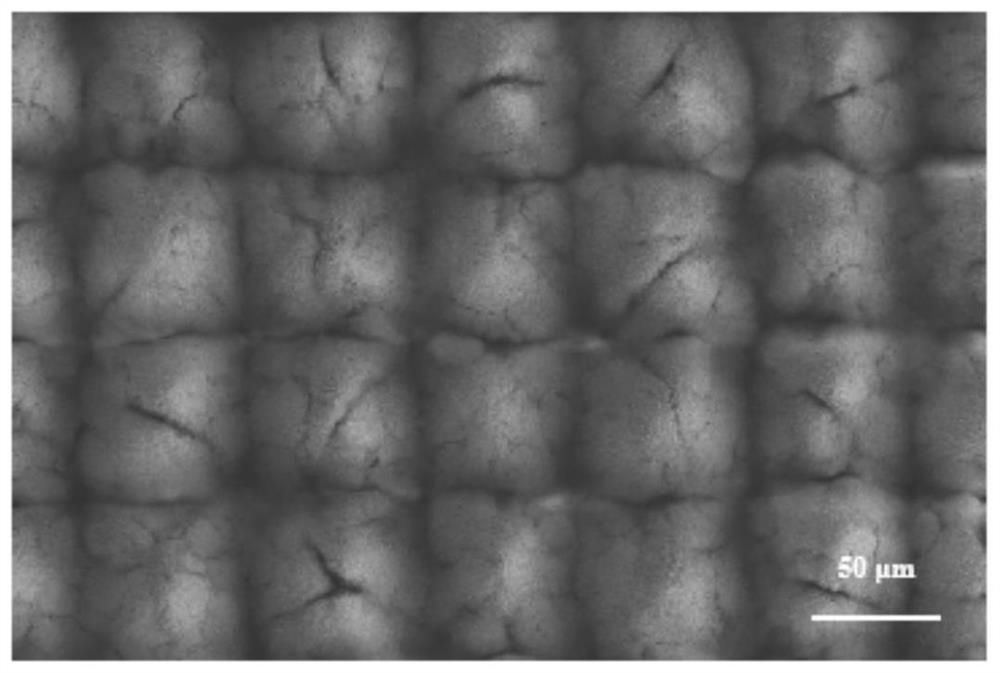
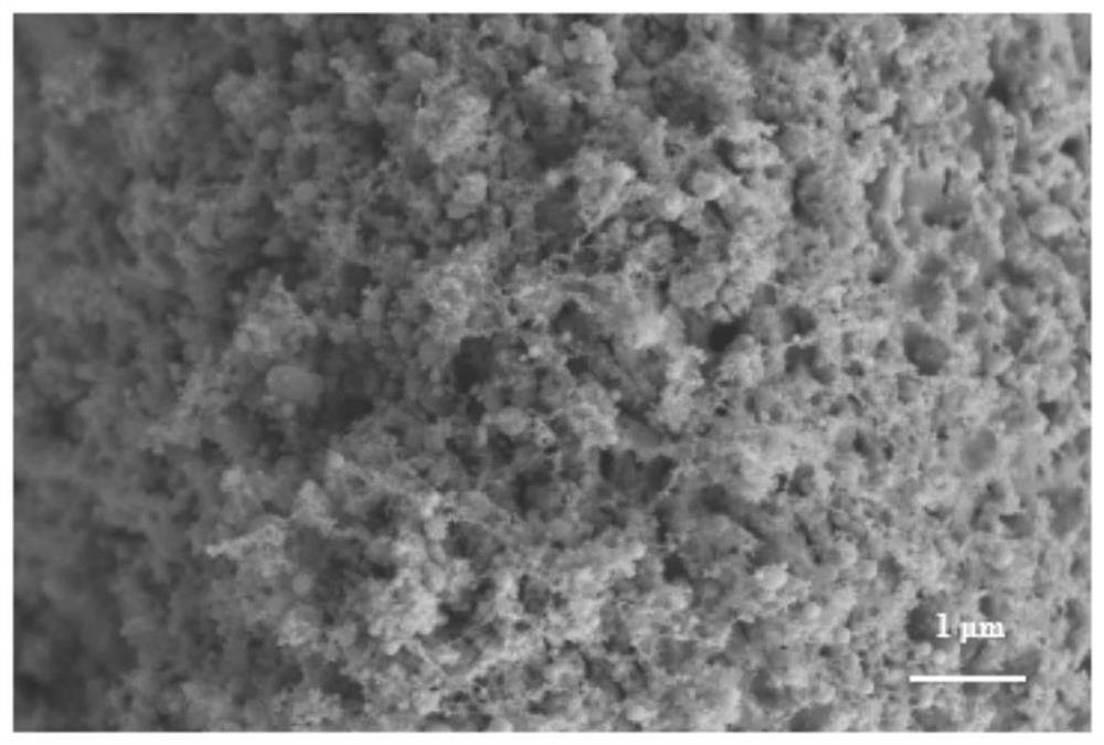
[0050] A clean superalloy substrate is provided, and a bonding layer, a first ceramic layer, a second ceramic layer and a composite coating are sequentially formed on the superalloy substrate, and a micro-nano composite structure is formed on the surface of the composite coating.

[0051] In some embodiments, the superalloy substrate can be a second-generation single crystal alloy, such as DD6, N5, etc., or a directional superalloy, such as DZ125, etc.

[0052] In some embodiments, the method of forming the NiCoCrAlY bonding layer may be electron beam physical vapor deposition, multi-arc ion plating, and the like.

[0053] The specific steps of the electron beam physical vapor deposition can be: prepare the superalloy substrate and the evapo...

Embodiment 1

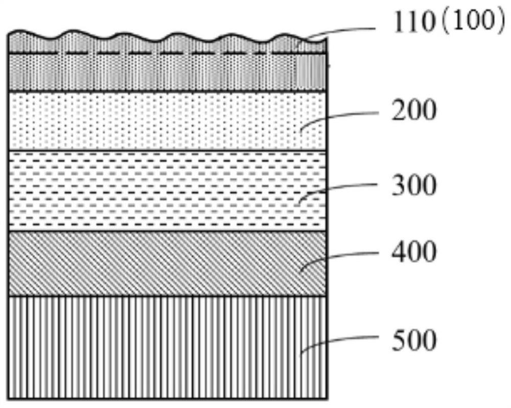
[0063] Such as figure 1 As shown, a PtNiAl bonding layer 400 (electroplating Pt aluminized)+YSZ first ceramic layer 300 (PS-PVD)+GYbZ second ceramic layer 200 (PS-PVD)+doped Al is prepared on the surface of a superalloy substrate 500 2 o 3 The composite structural thermal barrier coating of the GYbZ composite coating 100 (PS-PVD), the specific steps are as follows:

[0064] In the first step, the superalloy substrate 500 is ground, polished, and sandblasted on the surface. The superalloy is the second generation single crystal alloy (DD6 or N5) or directional superalloy DZ125;

[0065] In the second step, a PtNiAl bonding layer is prepared on the superalloy substrate 500 by means of electroplating and embedding infiltration, and the steps are as follows:

[0066] Diammonium platinum nitrite (Pt(NH 3 ) 2 (NO 2 ) 2 ), ammonium nitrate (NH 4 NO 3 ), sodium nitrite (NaNO 2 ), ammonia water (NH 3 ·H 2 O) mixing and preparing the Pt electroplating solution. Put the supe...


PUM

PropertyMeasurementUnit
Thicknessaaaaaaaaaa
Thicknessaaaaaaaaaa
Particle sizeaaaaaaaaaa

Abstract

The invention relates to the technical field of thermal barrier coatings, in particular to a composite coating, a preparation method thereof and a thermal barrier coating. A micro-nano composite structure is arranged on the surface of the composite coating, the composite coating comprises Al2O3-doped GYbZ, the GYbZ is Yb modified gadolinium zirconate, and the doping amount of Al2O3 is 5 mol%-20 mol%. Al2O3 can effectively inhibit growth of GYbZ crystal grains and nanoparticles in a micro-nano structure of the coating, so that the high-temperature sintering resistance and high-temperature stability of the composite coating are improved, and the high-temperature melting CMAS dredging capacity of a thermal barrier coating system for a long time at high temperature is guaranteed.

Description

technical field [0001] The invention relates to the technical field of thermal barrier coatings, in particular to a composite coating, a preparation method thereof, and a thermal barrier coating. Background technique [0002] Thermal barrier coatings (Thermal Barrier Coatings, TBCs), high-temperature structural materials, and high-efficiency air cooling are the three key technologies for turbine blades, the core hot-end components of advanced aero-engines. The application of thermal barrier coatings in aero-engines has greatly improved the engine's operating temperature and high-temperature gas corrosion resistance, greatly prolonging the service life of aero-engines, and has important military significance. As the service temperature and life of aero-engines continue to increase, one of the main chemical components is CaO-MgO-Al 2 o 3 -SiO 2 (referred to as CMAS) environmental deposits are increasingly harmful to the thermal barrier coating of engine blades. On the one h...

Claims


Application Information

Patent Timeline
IPC IPC(8): C23C14/22C23C14/02C23C14/08
CPCC23C14/22C23C14/08C23C14/025Y02T50/60
Inventor 郭洪波郭奕谦何雯婷
Owner BEIHANG UNIV
Why Eureka
Try Eureka