
Biomass-based multifunctional photo-thermal protective coating with photo-thermal temperature rise function and preparation method of biomass-based multifunctional photo-thermal protective coating

A protective coating and biomass technology, applied in the field of biomass-based multifunctional photothermal protective coating and its preparation, can solve the effect of stains on the photothermal performance of the deicing surface, cannot simultaneously take into account multiple protective effects, and photothermal conversion Poor efficiency and other problems, to overcome the lack of durability, reduce heat loss, and obtain simple effects

Pending Publication Date: 2022-04-15
SHAANXI UNIV OF SCI & TECH
View PDF7 Cites 0 Cited by
  • Summary
  • Abstract
  • Description
  • Claims
  • Application Information

AI Technical Summary

Problems solved by technology

[0005] The purpose of the present invention is to overcome the above-mentioned shortcomings of the prior art, and to provide a biomass-based multifunctional photothermal protective coating for photothermal heating and its preparation method. The present invention uses cellulose in nature as a raw material to prepare a A kind of hydrophobic hollow microtube with high photothermal conversion efficiency, and apply it to the field of superhydrophobic photothermal protective coating to solve the problems of existing coatings that cannot take into account multiple protective effects at the same time, toxic and harmful raw materials, not environmentally friendly, and deicing surfaces The photothermal performance is affected by stains, the photothermal conversion efficiency is poor, and the traditional deicing method is too expensive.

Method used


Image

  • Biomass-based multifunctional photo-thermal protective coating with photo-thermal temperature rise function and preparation method of biomass-based multifunctional photo-thermal protective coating
  • Biomass-based multifunctional photo-thermal protective coating with photo-thermal temperature rise function and preparation method of biomass-based multifunctional photo-thermal protective coating
  • Biomass-based multifunctional photo-thermal protective coating with photo-thermal temperature rise function and preparation method of biomass-based multifunctional photo-thermal protective coating

Examples


preparation example Construction

[0038] The invention discloses a rapid photothermal heating biomass-based multifunctional photothermal protective coating and a preparation method thereof. The preparation method specifically includes the following steps:

[0039] Step 1, putting cellulose into a tube furnace for calcination to obtain carbonized hollow microtubes (CHMT), the main component of which is carbon;

[0040] Specifically, the cellulose is put into a tube furnace for calcination, the temperature of the tube furnace is 400-1000° C., the heating rate is 1-15° C. / min, and the calcination time is 15-200 minutes to obtain carbonized hollow microtubes ( CHMT).

[0041] Wherein, the cellulose is biomass-based cellulose, which includes but not limited to one or more mixtures of bamboo fiber, cotton fiber, kapok fiber, wood fiber and absorbent cotton, and the hollow space formed by different cellulose Microtubules vary in size.

[0042] Step 2, adding CHMT to an organic solvent, and ultrasonically forming a ...

Embodiment 1

[0047]

[0048]

[0049] The kapok cellulose was put into a tube furnace for calcination. The temperature of the tube furnace was 400° C., the heating rate of the tube furnace was 3° C. / min, and the calcination time was 30 minutes to obtain hollow carbon microtubes (CHMT). CHMT was added to a mixture of ethanol (20 mL) and ethyl acetate (20 mL), and a uniform slurry A was formed by ultrasonication, wherein the concentration of CHMT was 4 mg / mL, the ultrasonic power was 60 W, and the ultrasonic time was 10 min.

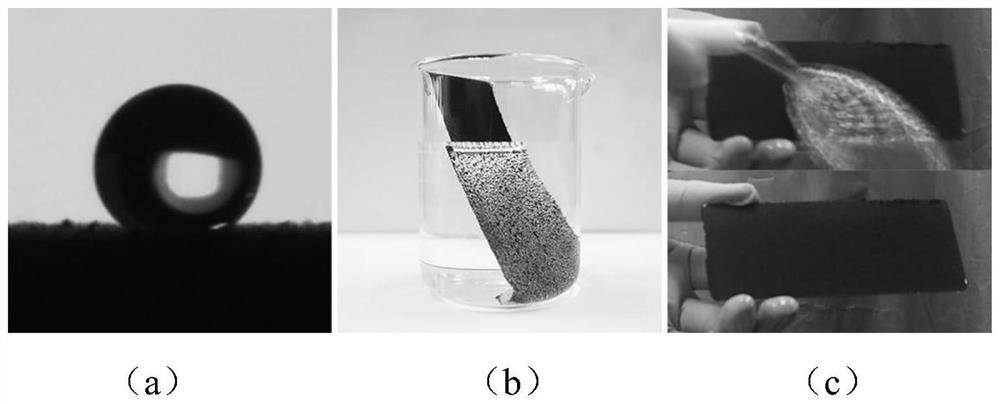
[0050] Add 0.95g of silicone resin and 0.5g of curing agent to the above mixed solution, stir at a speed of 1000r / min for 5min to obtain slurry B, then dip-coat the dispersed mixed solution on the wood substrate, at 110°C After curing for 2 hours, a hydrophobic photothermal deicing coating was obtained. Such as figure 1 As shown, the water droplet has a large contact angle and presents a spherical shape on the coating surface. At the same time, it can be seen th...

Embodiment 2

[0052]

[0053]

[0054] Bamboo fibers were put into a tube furnace for calcination. The temperature of the tube furnace was 600° C., the heating rate of the tube furnace was 5° C. / min, and the calcination time was 60 min to obtain hollow carbon microtubes (CHMT). CHMT was added to a mixture of ethanol (10 mL) and acetone (30 mL), and a uniform slurry A was formed by ultrasonication, wherein the concentration of CHMT was 8 mg / mL, the ultrasonic power was 60 W, and the ultrasonic time was 15 min.

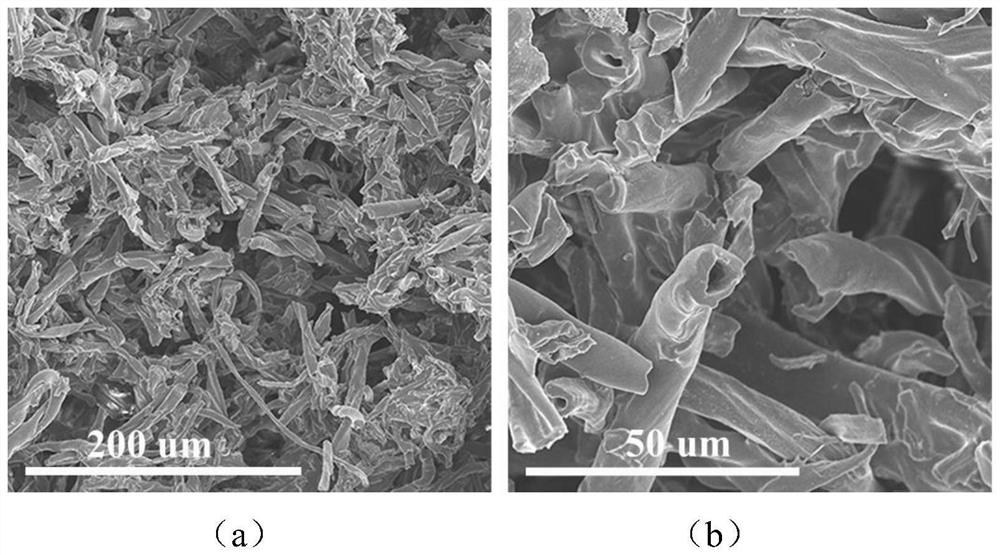
[0055] Add 1g of epoxy resin and 0.1g of curing agent to the above mixed solution, stir at a speed of 500r / min for 10min to obtain slurry B, and then spray the dispersed mixed solution on the glass substrate at a spraying angle of 70° , the distance between the spray gun and the surface of the substrate was 20 cm, and cured at 100 °C for 10 h to obtain a hydrophobic photothermal deicing coating. Such as figure 2 As shown, the scanning electron microscope analysis of the prepa...


PUM


Abstract

The invention discloses a photo-thermal heating biomass-based multifunctional photo-thermal protective coating and a preparation method thereof.The preparation method comprises the steps that cellulose is put into a tubular furnace to be calcined, carbonized hollow microtubes (CHMT) are obtained, then the CHMT is dispersed into an organic solvent, a certain amount of thermosetting resin and a certain amount of curing agent are added, and finally the coating is prepared. The coating is coated on the surface of a base material through a spraying or dip-coating process, and the multifunctional anti-icing and deicing coating is obtained after curing. The preparation process is simple, CHMT and resin are good in compatibility, construction of a three-dimensional network structure is facilitated, heat transfer is accelerated, meanwhile, heat loss can be reduced through the hollow structure, and the temperature of the coating can be increased more rapidly. And the prepared coating has excellent chemical stability and mechanical stability.

Description

technical field [0001] The invention belongs to the field of surface function protective materials, and relates to a biomass-based multifunctional photothermal protective coating with photothermal heating and a preparation method thereof. Background technique [0002] In daily life, the surface of objects is vulnerable to various damages, including pollutants, scratches, acid-base solutions, sunlight, rain impact, ice and snow and other extreme environments, which seriously affect the service performance of materials and cause a lot of energy waste , does not meet the relevant requirements of carbon neutrality, and it is urgent to develop materials with excellent durability. Among them, the functional protective coating has become the first choice of people because of its wide range of universality, excellent protection ability and relatively low cost. However, most coatings have a single function and cannot meet the actual needs under different working conditions. Therefor...

Claims


Application Information

Patent Timeline
IPC IPC(8): C09D183/04C09D163/00C09D179/08C09D161/06C09D7/61
Inventor 李永李浩杨欣月宋浩杰杨进贾晓华邵丹王思哲
Owner SHAANXI UNIV OF SCI & TECH
Learn More