Methods and structures for removing ice from surfaces

A technology of ice and snow coating, applied in the field of removing ice and systems on the surface, can solve the problems of high cost of deicing, low ice friction coefficient, increased wind resistance, etc.

Inactive Publication Date: 2004-03-31
TRUSTEES OF DARTMOUTH COLLEGE THE
View PDF0 Cites 0 Cited by
  • Summary
  • Abstract
  • Description
  • Claims
  • Application Information

AI Technical Summary

Problems solved by technology

[0006] There are deficiencies and difficulties in these existing technologies
First, propeller-propelled aircraft do not have jet engines
Second, the rubber tubes at the front of the wings increase wind resistance
Third, ...

Method used


Image

  • Methods and structures for removing ice from surfaces
  • Methods and structures for removing ice from surfaces
  • Methods and structures for removing ice from surfaces

Examples


example 1

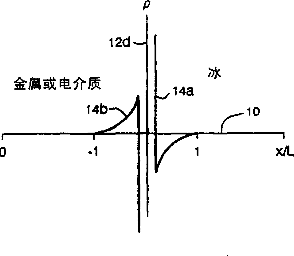
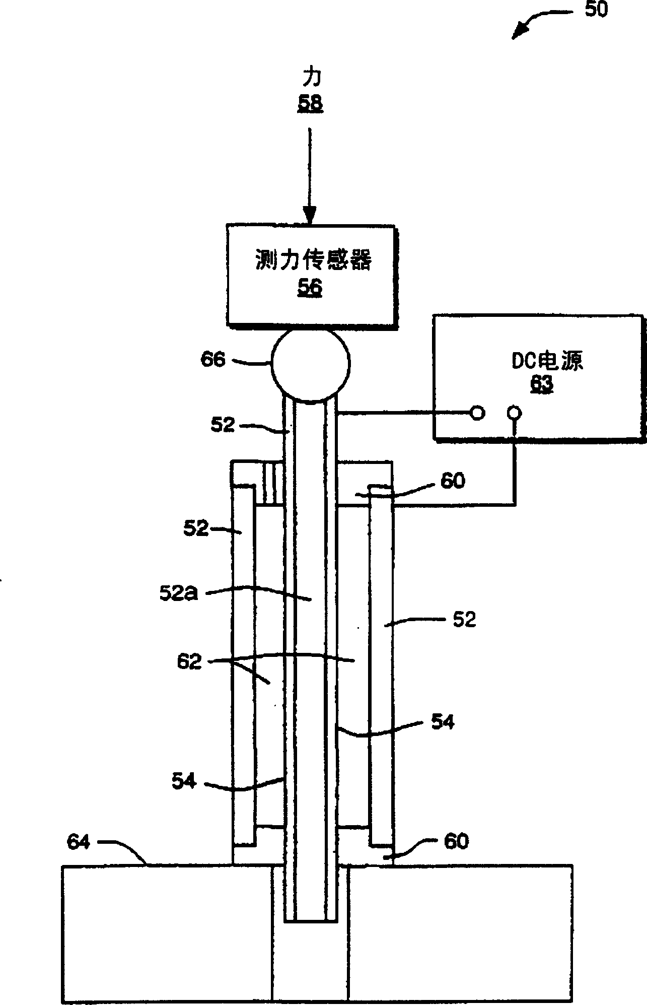
[0067] use figure 2 System 50 is shown. The effect of DC bias on icing on solid metal was studied. After the space between the two steel pipes 52 is filled with 0.5% sodium chloride aqueous solution, the system 50 is placed in a cold room with a temperature of -10°C. Multiple systems 50 are filled with saline. The salt content in the water is the same as normal sea water. All samples were placed in the cold chamber for 3 hours prior to testing, a period of time sufficient to allow the water to freeze and the internal stress of the resulting ice to be relieved. The maximum shear strength of the ice-steel interface 54 was measured when the sample was loaded at a constant strain rate of 100 μm / min (applied force 58 via load cell 56). A DC bias in the range of -21v - +21v was applied and maintained between the stainless steel tubes 52 at the beginning of loading. A Teflon cover 60 allows movement of the inner tube 52a relative to the ice. A DC power supply 63 provided the D...

example 2

[0115] Figure 7 An embodiment of the invention is shown for ice formation on a SAM. A chrome layer 204 is formed on a quartz substrate 202 . On the chrome layer 204 is a gold layer 206 . Then, a self-assembled monomolecular adsorption layer (SAM) 208 is formed on the gold-plated layer 206 . There is a drop of water or ice 210 on the top surface of the SAM 208. A DC power source 212 is connected to the water or ice drop 210 and an electrometer 214 . Electrometer 214 is connected to gold plating layer 206 . The electrometer 214 measures the current density at the interface when the DC bias voltage of the power supply 212 and the hydrophobic property of the SAM 208 are changed in a coulometric manner.

[0116] SAM208 was prepared using gold-coated optics. The gold-plated layer 206 is rinsed with ethanol and then blown dry with nitrogen gas flow. Then soak the gold-plated layer 206 with the above-mentioned suitable solution for 12-36 hours to obtain hydrophilicity or hydro...

example 3

[0142] with Pb 3 MgNb 2 o 9 Take the calculation of heating power as an example. In this example, a medium-voltage transmission line is used whose √V 2 =10kV, the wire diameter is 1cm=2×radius. The electric field strength on the surface of the wire is:

[0143] ( 3 ) - - - E ≈ V ln ( L r ) r ≈ 3 kv / cm

[0144] Among them, L is the distance between lines (L=1m). With each data, namely E 2 =3×10 5 V / M, ω=2H×60Hz, ε’=104 and tanδ=10, calculate W(1mm, 60Hz)=4.5×10 5 W / M 3 . So, say a 1mm thick film generates 450W / M 2 , the heat is generally sufficient to melt the ice.

[0145] 1mm thick Pb at 300kV, 100kHz frequency 3 MgNb 2 o 9 The heatin...


PUM

PropertyMeasurementUnit
Adsorptionaaaaaaaaaa

Abstract

In one embodiment, a system for modifying ice adhesion strength of ice adhered to an object. The system includes an electrode that is electrically insulated from the object and a DC source, e.g., a battery, coupled to the object and the electrode. The source generates a DC bias to an interface between the ice and the object when the ice completes the circuit. The system preferably includes an electrically insulating material disposed between the object and the electrode. In another embodiment, a coating comprising a ferroelectric, lossy dielectric, ferromagnetic or semiconductor material is applied to an object. Electromagnetic energy causes the coating to generate heat, which melts snow and ice.

Description

[0001] This invention was made with United States Government support; the United States Government has certain rights in this invention. Support from the U.S. Government was specifically granted by Army Research Institute grant fund #DAAH04-95-1-0189 and National Science Foundation grant fund #MSS-9302792. technical field [0002] The present invention relates to methods, systems and structures for heating ice and snow and changing the strength of ice adhesion between the ice and selected objects. Background technique [0003] Ice that adheres to certain surfaces causes many problems. For example, excessive ice buildup on the wings of an aircraft can endanger the safety of the aircraft and its passengers. Ice accumulation on the hull causes navigation difficulties, increased power costs and increased unsafe factors when navigating in ice water. Scraping ice off a car windshield is a cumbersome chore that can obscure a driver's vision and make driving unsafe if not removed....

Claims


Application Information

Patent Timeline
IPC IPC(8): B64D15/00B64D15/12E01C11/26E01D19/00H05B3/00H05B3/56H05B3/84
CPCB64D15/12H05B3/00H05B3/56B82Y30/00E01C11/265E01D19/00H05B3/84H05B2214/02
Inventor 维克托·彼得连科查尔斯·沙利文
Owner TRUSTEES OF DARTMOUTH COLLEGE THE
Why Eureka
Try Eureka