Vacuum electron beam welding method for low-activation martensitic steel and nuclear fusion reactor

A vacuum electron beam and martensitic steel technology, applied in electron beam welding equipment, welding equipment, welding/welding/cutting items, etc., can solve the problems of low production efficiency, complicated process, high production cost, etc., and achieve weldment deformation Small, simple process, small splash effect

Pending Publication Date: 2022-06-07
合肥聚能电物理高技术开发有限公司
View PDF5 Cites 2 Cited by
  • Summary
  • Abstract
  • Description
  • Claims
  • Application Information

AI Technical Summary

Problems solved by technology

However, the process still requires two heat treatment steps before and after electron beam welding, which has the defects of complex process, high production cost and low production efficiency. In addition, there is still room for improvement in reducing the risk of weld cracking

Method used


Image

  • Vacuum electron beam welding method for low-activation martensitic steel and nuclear fusion reactor
  • Vacuum electron beam welding method for low-activation martensitic steel and nuclear fusion reactor
  • Vacuum electron beam welding method for low-activation martensitic steel and nuclear fusion reactor

Examples


Embodiment 1

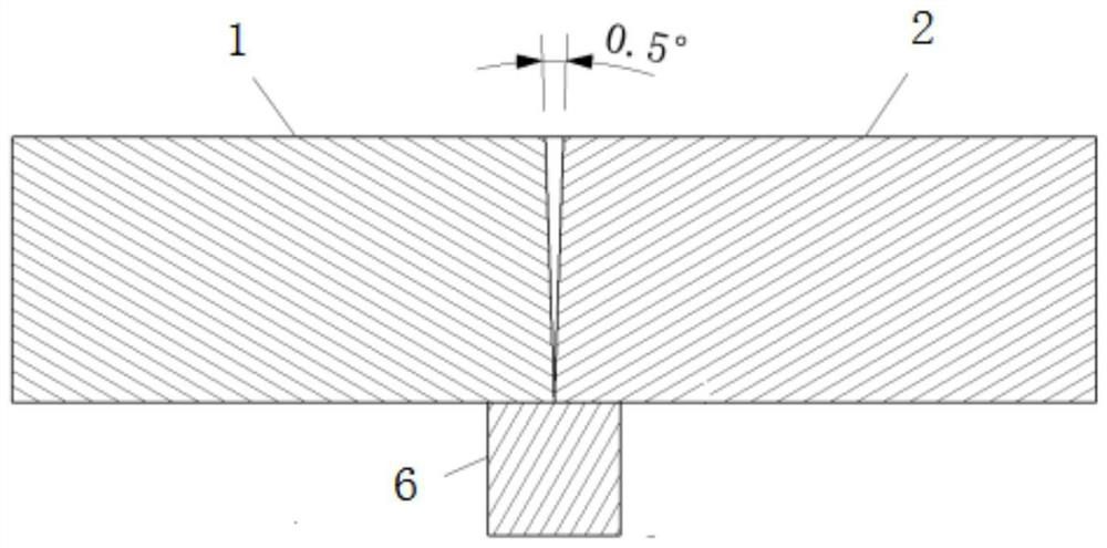
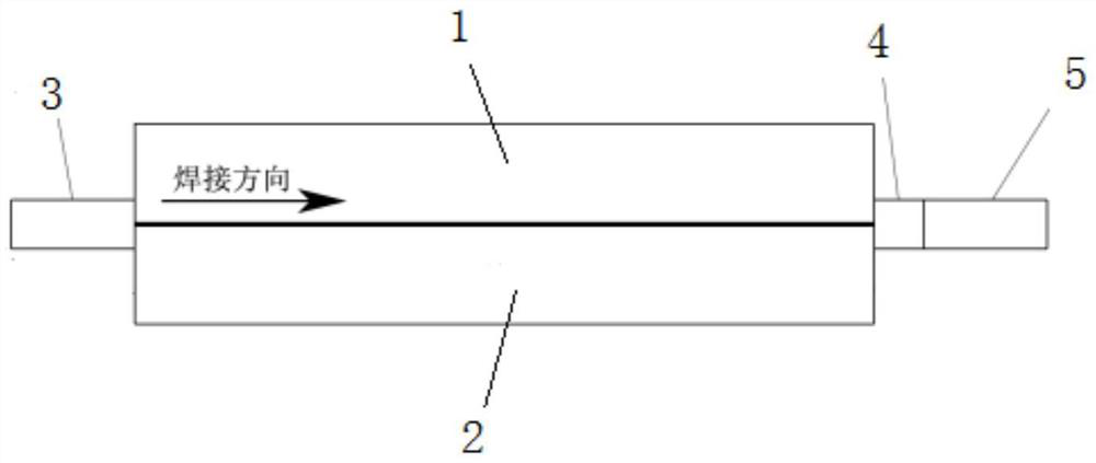
[0029] like figure 1 As shown, the two clam steel plates are strip-shaped, the first steel plate 1 and the second steel plate 2, the plate thickness δ: 20mm, the length 300mm, the width 150mm, and the welding penetration is required;

[0030] A method for vacuum electron beam welding of low-activation martensitic steel provided by this embodiment includes the following steps:

[0031] (1) The adjacent parts to be welded of the two first steel plates 1 and the second steel plate 2 are processed into a V-shaped groove of 0.5° (the effect of the tiny V-shaped groove of 0.5° can alleviate the low activation martensitic steel. The stress concentration of the weld during the welding process, and at the same time of the heat input, can significantly improve the weld penetration compared with the non-groove weld, thereby ensuring that a large weld can be obtained with a very small heat input. Penetration, reducing the risk of weld cracking, and reducing the advantages of deformation ...

Embodiment 2

[0042] The two clam steel plates are strip-shaped, the first steel plate 1 and the second steel plate 2, the plate thickness δ: 4mm, the length 300mm, the width 150mm, and no penetration is required;

[0043] A method for vacuum electron beam welding of low-activation martensitic steel provided by this embodiment includes the following steps:

[0044] (1), the adjacent to-be-welded parts of two first steel plates 1 and second steel plates 2 are processed into a V-shaped groove of 0.5°;

[0045] (2), polish the first steel plate 1 and the second steel plate 2 to be welded and the metal surface in the peripheral 40mm range with fine sandpaper to expose metallic luster;

[0046] (3), use the demagnetizer to demagnetize the first steel plate 1 and the second steel plate 2, and the residual magnetic induction intensity is checked to be 1.5 Gauss;

[0047] (4), clean the first steel plate 1 and the second steel plate 2 with water, and then wipe the surface of the workpiece with a sil...

Embodiment 3

[0055] The difference from Example 1 is that the two clam steel plates are annular clam steel plates with closed welds, the steps are the same as those of Example 1, and the beam attenuation length at the end of the welding is greater than 6 times the penetration depth.


PUM

PropertyMeasurementUnit
widthaaaaaaaaaa
lengthaaaaaaaaaa
lengthaaaaaaaaaa

Abstract

The invention discloses a low-activation martensitic steel vacuum electron beam welding method and a nuclear fusion reactor. The method comprises the steps of machining a V-shaped groove, placing a leading-in plate, a transition leading-out plate, a leading-out plate and a base plate at the welding position, conducting positioning welding, conducting penetration welding and the like. The nuclear fusion reactor comprises a component formed by welding the low-activation martensitic steel through the vacuum electron beam welding method. The welding method is simple, the welding seam which is free of cracks, small in splashing and smooth in appearance fish scale line transition can be obtained, the B-level welding seam requirement of ISO13919-1 is met, a weldment is small in deformation, the room-temperature tensile strength of a welded joint is larger than that of base metal, and a lateral bending test of the welded joint is qualified.

Description

technical field [0001] The invention relates to a welding method, in particular to a vacuum electron beam welding method for low-activation martensitic steel in a nuclear fusion reactor. Background technique [0002] Low activation martensitic steel has low thermal expansion coefficient, high thermal conductivity, excellent mechanical properties, and low irradiation swelling behavior, which is an ideal structural material in nuclear fusion reactors. [0003] Publication number CN104400203A, the patent name is "an electron beam welding process suitable for encapsulation and molding of martensitic steel high-density flow channels", discloses a fusion reactor cladding low activation martensitic steel cooling component high The electron beam welding method of density runner encapsulation, the runner formed by this method has no defects such as pores and cold / hot cracks, and has the advantages of small welding deformation, which solves the problem of high-density runner packaging...

Claims


Application Information

Patent Timeline
Patent Type & Authority Applications(China)
IPC IPC(8): B23K15/00B23K15/06B23K103/04
CPCB23K15/0053B23K15/06B23K2103/04Y02E30/10
Inventor 刘振飞吴杰峰王丽芳文伟张勇马建国李波沈旭慕香红
Owner 合肥聚能电物理高技术开发有限公司
Why Eureka
Try Eureka