
Sludge recycling treatment system

The technology of a treatment system and a flue gas treatment system is applied in the field of sludge recycling and reuse treatment system, which can solve the problems of unsatisfactory treatment effect, high energy utilization rate, poor operation stability, etc., to maintain temperature, realize waste heat utilization, maintain a stable effect

Active Publication Date: 2022-07-12
JIANGSU QUANNENG ELECTROMECHANICAL EQUIP ENG LTD BY SHARE LTD
View PDF11 Cites 0 Cited by
  • Summary
  • Abstract
  • Description
  • Claims
  • Application Information

AI Technical Summary

Problems solved by technology

[0008] Aiming at the deficiencies of the prior art, the object of the present invention is to provide a sludge recycling treatment system. After the wet sludge is dried by the sludge drying system, it can be incinerated in an incinerator without adding auxiliary fuel. It can be self-sustained incineration, which saves auxiliary fuel expenses and reduces operating costs; the heat generated by sludge incineration is reused for sludge drying through the heat energy recovery system, forming a closed loop of energy recycling. The system has a high energy utilization rate and can solve existing Due to the technical problems of high system operating cost, poor operation stability and unsatisfactory treatment effect, a recycling treatment system integrating sludge drying-incineration-tail gas treatment has been realized.

Method used


Image

  • Sludge recycling treatment system
  • Sludge recycling treatment system
  • Sludge recycling treatment system

Examples


Embodiment Construction

[0031] The technical solutions in the embodiments of the present invention will be clearly and completely described below with reference to the accompanying drawings in the embodiments of the present invention. Obviously, the described embodiments are only a part of the embodiments of the present invention, but not all of the embodiments. Based on the embodiments of the present invention, all other embodiments obtained by those of ordinary skill in the art without creative efforts shall fall within the protection scope of the present invention.

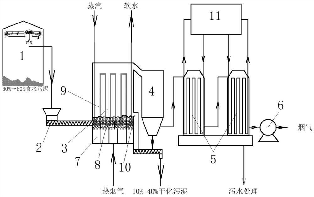
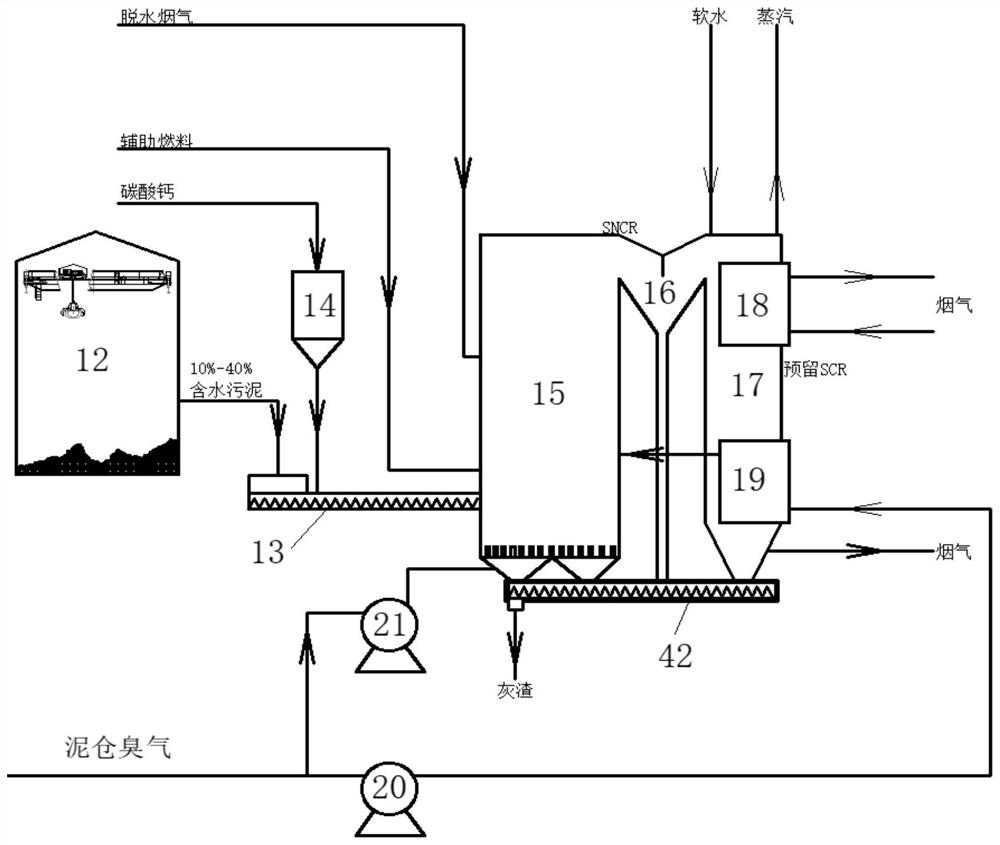
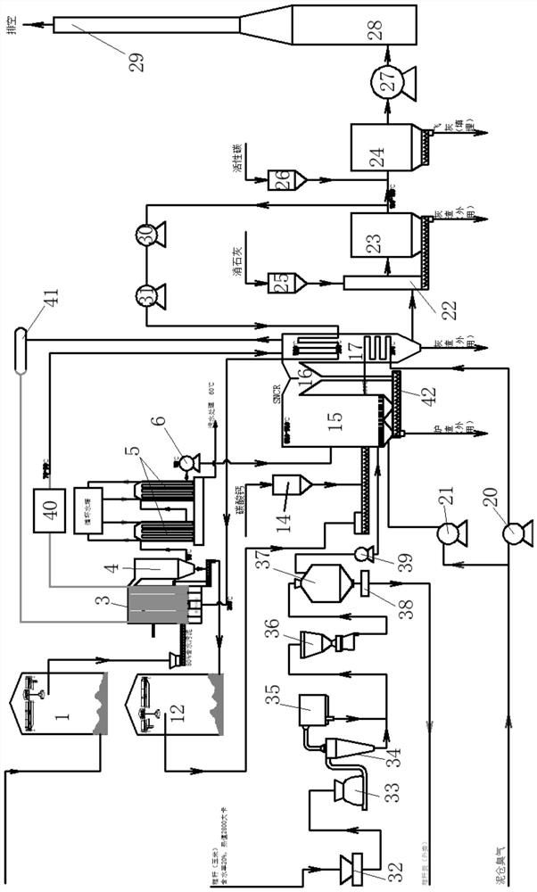
[0032] see Figure 1-3 , a sludge recycling treatment system, including sludge drying system, sludge incineration system, flue gas treatment system and straw gasification system;

[0033] The sludge drying system includes a wet sludge pit 1, a feeding screw 2, a fluidized bed dryer 3, a first cyclone dust collector 4, a secondary cooler 5 and a first induced draft fan 6 connected in sequence; The fluidized bed dryer 3 is provided with ...


PUM


Abstract

The invention discloses a sludge recycling treatment system which comprises a sludge drying system, a sludge incineration system, a flue gas treatment system and a straw gasification system. The sludge drying system comprises a wet sludge pit, a feeding screw conveyor, a fluidized bed dryer, a first cyclone dust collector, a secondary cooler and a first induced draft fan which are connected in sequence; the sludge incineration system comprises a dry sludge pit, a stokehole feeding system, a fluidized bed incinerator, a settling chamber and a waste heat boiler which are connected in sequence; and a calcium carbonate quantitative feeder is arranged above the stokehole feeding system in parallel. According to the sludge recycling treatment system provided by the invention, flue gas generated by sludge incineration is used as a pre-drying heat source for recycling, so that the technical problems of high operation cost, poor operation stability and non-ideal treatment effect of an existing system can be solved, and stable, harmless and resource utilization of the sludge is realized.

Description

technical field [0001] The invention belongs to the technical field of sludge treatment, and in particular relates to a sludge recycling and reuse treatment system. Background technique [0002] With the increasing population and rapid economic development in China, by the end of 2015, my country had built more than 3,910 urban sewage treatment plants, and the daily treatment capacity of sewage treatment plants had reached 167 million cubic meters per day. As a derivative of sewage, in 2015 The annual municipal sludge (with a moisture content of 80%) produces 30 million to 40 million tons. It is estimated that by 2020, my country's municipal sludge output will reach 60 to 90 million tons. [0003] Sludge is the concentration of pollutants in the water treatment process. It is mainly composed of microbial cell groups and their disintegration products. In addition to high organic matter content, it also contains a large number of heavy metal ions, pathogenic bacteria and other ...

Claims


Application Information

Patent Timeline
Patent Type & Authority Applications(China)
IPC IPC(8): C02F11/13F23G7/00F23G5/04F23G5/46F23J15/00F23J15/02F23J15/06C10B53/02C10B57/00
CPCC02F11/13F23G7/001F23G5/04F23G5/46F23J15/003F23J15/025F23J15/06C10B53/02C10B57/005Y02P20/129
Inventor 钱重羽
Owner JIANGSU QUANNENG ELECTROMECHANICAL EQUIP ENG LTD BY SHARE LTD
Learn More