
Flue gas waste heat recovery system with heat pump and gas-water surface type heat exchanger coupled

A recovery system and flue gas waste heat technology, applied in heat pumps, lighting and heating equipment, refrigerators, etc., can solve problems such as water vapor environmental pollution, flue gas temperature rise, boiler efficiency reduction, etc., to achieve energy saving and energy saving efficiency The effect of optimization and energy-saving efficiency improvement

Pending Publication Date: 2022-07-29
TSINGHUA UNIV +2
View PDF6 Cites 0 Cited by
  • Summary
  • Abstract
  • Description
  • Claims
  • Application Information

AI Technical Summary

Problems solved by technology

The increased heat loss will reduce the boiler efficiency by 7-10%
However, GGH can only increase the flue gas temperature, and cannot recover heat
[0009] (2) Large water consumption:
According to actual measurements, a 600MW power plant boiler using wet desulfurization technology consumes more than 130t / h of water, which not only consumes a lot of water, but also produces water vapor that is likely to cause environmental pollution
[0011] (3) Cause smog and pollute the environment:

Method used


Image

  • Flue gas waste heat recovery system with heat pump and gas-water surface type heat exchanger coupled
  • Flue gas waste heat recovery system with heat pump and gas-water surface type heat exchanger coupled
  • Flue gas waste heat recovery system with heat pump and gas-water surface type heat exchanger coupled

Examples


Embodiment 1

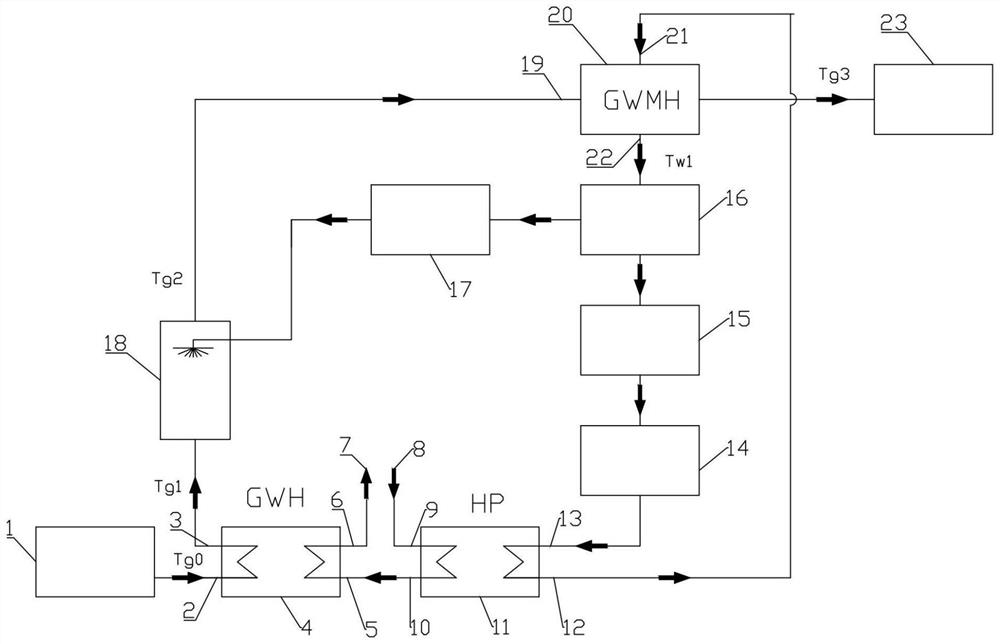
[0038] like figure 2 As shown in the figure, a flue gas waste heat recovery system coupled with a heat pump and an air-to-water surface heat exchanger includes a boiler waste heat recovery system and a heat user heating system; the boiler waste heat recovery system also includes a tail flue 1 connected to the furnace. , the air-water surface heat exchanger 4 connected to the tail flue 1, the desulfurization tower 18 connected to the air-to-water surface heat exchanger 4, the air-water mixing heat exchanger 20 connected to the desulfurization tower 18, and the The water circulation system connected with the water mixing heat exchanger 20; the heat user heating system is connected with the air-water surface heat exchanger 4 and the water circulation system at the same time.

[0039] Furnace: refers to the equipment that can generate flue gas, and the equipment can be boilers, kilns, smelting furnaces, gas engines, etc., and mainly refers to coal-fired boilers in this embodiment...

Embodiment 2

[0057] The specific process is:

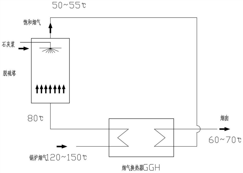
[0058] The tail flue gas of the boiler or other coal-fired and gas-fired furnaces enters the air-water surface heat exchanger through the tail flue, and is cooled by heat exchange, and the flue gas temperature is changed by T g0 down to T g1 , and then enter the desulfurization tower. In general, the boiler tail flue gas temperature T g0 is about 120°C. If it directly enters the desulfurization tower, the temperature of the desulfurization tower will rise, and the discharge temperature will reach above 60 °C, which consumes a lot of water and heat, and causes pollution such as haze in the environment. If the temperature of the flue gas at 120°C drops to 80°C through the air-water surface heat exchanger, and then enters the desulfurization tower, the temperature of the flue gas from the desulfurization tower is about 50-52°C, and the water vapor and water consumption are greatly reduced.

[0059] In the background art, wet desulfurization c...

Embodiment 3

[0070] This embodiment is a practical application scheme of Embodiment 1.

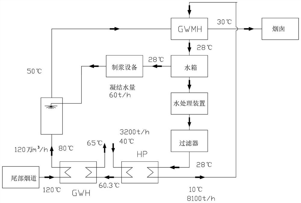
[0071] A large coal-fired thermal power plant recovers the waste heat from wet desulfurization flue gas for heat supply. The basic parameters of the power plant are as follows:

[0072] Power plant power generation: 350MW;

[0073] Flue gas flow after desulfurization: 1.2 million m 3 / h;

[0074] Flue gas water vapor content: 15%;

[0075] Heating temperature: 60℃;

[0076] Heating and return water temperature: 38 to 45 °C (take the design value of 40 °C);

[0077] The circulating water volume of the heating network: ∠4000t / h.

[0078] The system of the present application is used to recover the waste heat of the flue gas, wherein the gas-water mixing heat exchanger adopts a spray tower for heat generation. The simplified thermal system diagram is shown in image 3 , and label the temperature of each node:

[0079] According to the above parameters, the relevant data are calculated as follows: ...


PUM


Abstract

The invention discloses a flue gas waste heat recovery system with a heat pump and a gas-water surface type heat exchanger coupled. The flue gas waste heat recovery system comprises a boiler waste heat recovery system and a heat consumer heat supply system. The boiler waste heat recovery system further comprises a tail flue connected with the boiler, a gas-water surface type heat exchanger connected to the tail flue, a desulfurizing tower connected with the gas-water surface type heat exchanger, a gas-water mixing heat exchanger connected with the desulfurizing tower and a water circulation system connected with the gas-water mixing heat exchanger. The heat consumer heat supply system is connected with the gas-water surface type heat exchanger and the water circulation system at the same time. According to the flue gas waste heat recovery system with the heat pump and the gas-water surface type heat exchanger coupled, the flue gas temperature is reduced, meanwhile, waste heat of flue gas can be recovered and utilized, meanwhile, flue gas sensible heat and water vapor latent heat after desulfurization are recovered, and the energy-saving efficiency of the whole system is improved by 10% or above.

Description

technical field [0001] The present application relates to the field of waste heat recovery, in particular to a flue gas waste heat recovery system in which a heat pump is coupled with a gas-water surface heat exchanger. Background technique [0002] Energy saving, carbon reduction, and haze control are major issues of concern to our country and even the world. [0003] Large-scale power plants and iron and steel plants are today's major energy consumers, and their carbon emissions in the production process are at the forefront of enterprises, and their production and exhaust gas treatment have also greatly contributed to the formation of smog. The technologies of flue gas desulfurization, waste heat recovery of flue gas, and exhaust gas treatment of large power plants and iron and steel plants are urgently needed by the country. [0004] my country's coal-fired power generation accounts for about 70% of the total power generation, which is much higher than that of other cou...

Claims


Application Information

Patent Timeline
Patent Type & Authority Applications(China)
IPC IPC(8): F23J15/00F23J15/06F23J15/02F25B30/06
CPCF23J15/006F23J15/06F23J15/02F25B30/06F23J2215/20
Inventor 单明赖泽民杨旭东刘彦青马荣江余南阳庞智成车韶伟
Owner TSINGHUA UNIV
Learn More