
Preparation of grating device by utilizing ultrashort laser pulse and method for implementing holographic storage

A technology of ultra-short lasers and lasers, which is applied to optical components, instruments, light guides, etc., and can solve problems such as slow writing speed, low production efficiency, and small information storage capacity

Inactive Publication Date: 2004-12-29
PEKING UNIV
View PDF0 Cites 0 Cited by
  • Summary
  • Abstract
  • Description
  • Claims
  • Application Information

AI Technical Summary

Problems solved by technology

[0004] In the field of optical holographic storage and information processing, the traditional holographic writing method is basically single-photon absorption holographic exposure technology, which has slow writing speed, low production efficiency, small information storage capacity, and cannot be stored in multi-layer high density.

Method used


Image

  • Preparation of grating device by utilizing ultrashort laser pulse and method for implementing holographic storage
  • Preparation of grating device by utilizing ultrashort laser pulse and method for implementing holographic storage
  • Preparation of grating device by utilizing ultrashort laser pulse and method for implementing holographic storage

Examples


Embodiment 1

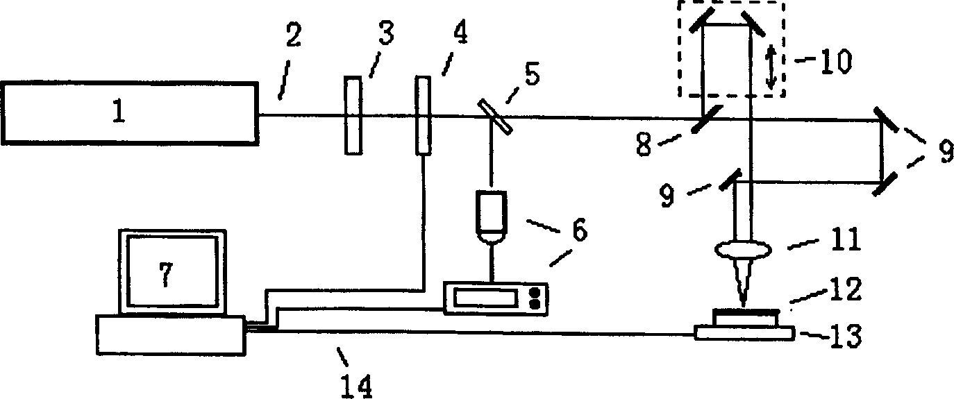
[0079] Such as figure 1 As shown, the ultrashort pulse laser 1 adopts a titanium sapphire femtosecond laser, the wavelength of the output laser beam is 800nm ​​(nanometer), the pulse width is 120fs (femtosecond), and the average power of the laser is 700mW, which is controlled by an energy attenuator 3 Write the magnitude of the laser energy, the shutter 4 selects a single laser pulse, the beam splitter 5 splits a small part of light and uses the energy meter 6 to detect the energy. The single pulse energy of the laser beam 2 is about 400uJ, and the laser beam is divided into two beams of the same energy by the half-mirror 8, one of which passes through an optical delay line 10, and the other beam is reflected by the mirror 9, and at the same time, the focusing The lens 11 is focused on the sample 12 , and the fine-tuning mirror 9 and the focusing lens 11 allow the two beams of light to overlap on the surface of the sample 12 . The sample moving platform 13 controls the posit...

Embodiment 2

[0089] Such as figure 2 As shown, the ultrashort pulse laser 1 adopts a titanium sapphire femtosecond laser, and the output laser beam 2 has a wavelength of 800nm ​​(nanometer), a pulse width of 120fs (femtosecond), and an average laser power of 700mW, which is controlled by an energy attenuator 3 Write the magnitude of the laser energy, the shutter 4 selects a single laser pulse, the beam splitter 5 splits a small part of light and uses the energy meter 6 to detect the energy. The single pulse energy of the laser beam 2 is about 400 μJ. After the beam splitter 15, the laser light is divided into beams with the same energy and symmetrical distribution, collimated by the collimator lens 17, and then two symmetrical beams are selected by the aperture diaphragm array 16, and focused on the sample 12 by the focusing lens 18 at the same time , the two beams of light coincide at the position on the surface of the sample 12 . The sample moving platform 13 controls the position of ...


PUM


Abstract

The invention provides a method of preparing diffraction-grating devices by using ultra-short laser pulse and that of realizing the holographic memory. The former method is as follows: use the spectra system to separate the ultra-fast laser pulse into two or more beams which arrive on the surface of in the body of double-photon absorbing polymer materials and overlap in time and space to obtain the interference stripes; by modualting the parameters of the beam number, the included angles and phases between eacho ther, intensity and so on, prepare one-dimensional, two-dimensional or three-dimensional minute-cycle diffraction-grating structure. The latter method is as follows: one separated beam in the former method is coupled with the information signal by space-light modulator and the information signal beam interferes with the reference beam,

Description

Technical field: [0001] The invention belongs to the technical field of grating and optoelectronic device preparation and the technical field of optical holography and information processing. Background technique: [0002] In the current high-tech field, various photonics and optoelectronic devices are continuously integrated, requiring smaller and smaller sizes, so it is technically necessary to prepare microstructures with higher precision. Gratings are common basic components, and are widely used in devices such as waveguide gratings (fiber gratings), grating couplers, wavelength division multiplexing communication components, and splitters in the communication field. Therefore, the precision preparation technology of the grating occupies a very important position. [0003] Traditional grating processing methods include mechanical scribing, ion beam etching, ultraviolet writing and holographic exposure. The first two methods can only make gratings on the surface of the ...

Claims


Application Information

Patent Timeline
Patent Type & Authority Patents(China)
IPC IPC(8): G02B6/124
Inventor 蒋红兵郭亨长郭红沧杨宏龚旗煌
Owner PEKING UNIV
Learn More