Electric soldering iron tip and electric soldering iron

A soldering iron tip, electric soldering iron technology, applied in the directions of soldering iron, welding position, coating, etc., can solve the problems of difficult temperature control of temperature difference, deterioration of heat conduction, short circuit, etc., to improve oxidation resistance, excellent oxidation resistance, and improve performance Effect

Inactive Publication Date: 2003-05-21
HAKKO CO LTD
View PDF1 Cites 6 Cited by
  • Summary
  • Abstract
  • Description
  • Claims
  • Application Information

AI Technical Summary

Problems solved by technology

[0011] In addition, in terms of structure, when the above-mentioned soldering iron tip 3 is installed on the ceramic heater 5 for heating, due to the presence of an air layer on the inner surface of the cylinder part of the soldering iron tip 3, it will be violently oxidized to produce CuO or Cu 2 Scale such as O not only deteriorates heat conduction, but also causes failures such as short circuits
[0012] In addition, since the tip of the soldering iron is a freely pluggable structure, there is a narrow gap between the inner surface of the inner tube 4 and the outer peripheral portion of the ceram

Method used


Image

  • Electric soldering iron tip and electric soldering iron
  • Electric soldering iron tip and electric soldering iron
  • Electric soldering iron tip and electric soldering iron

Examples


Embodiment 1

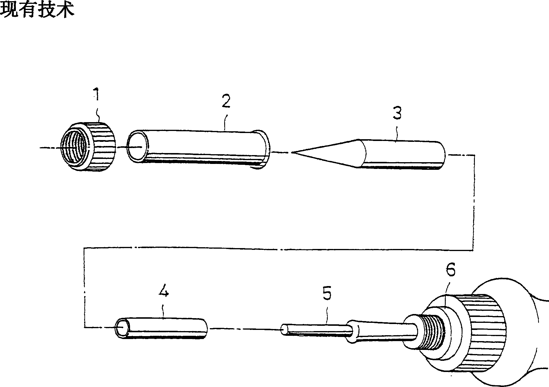
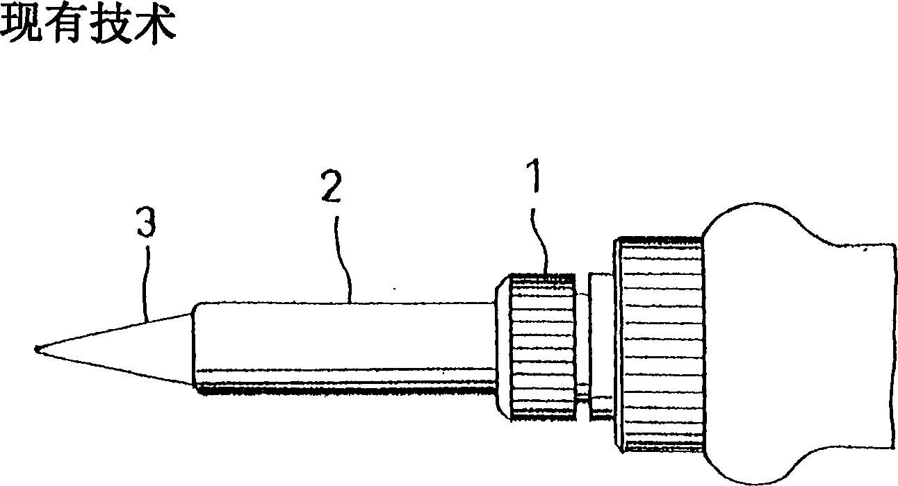
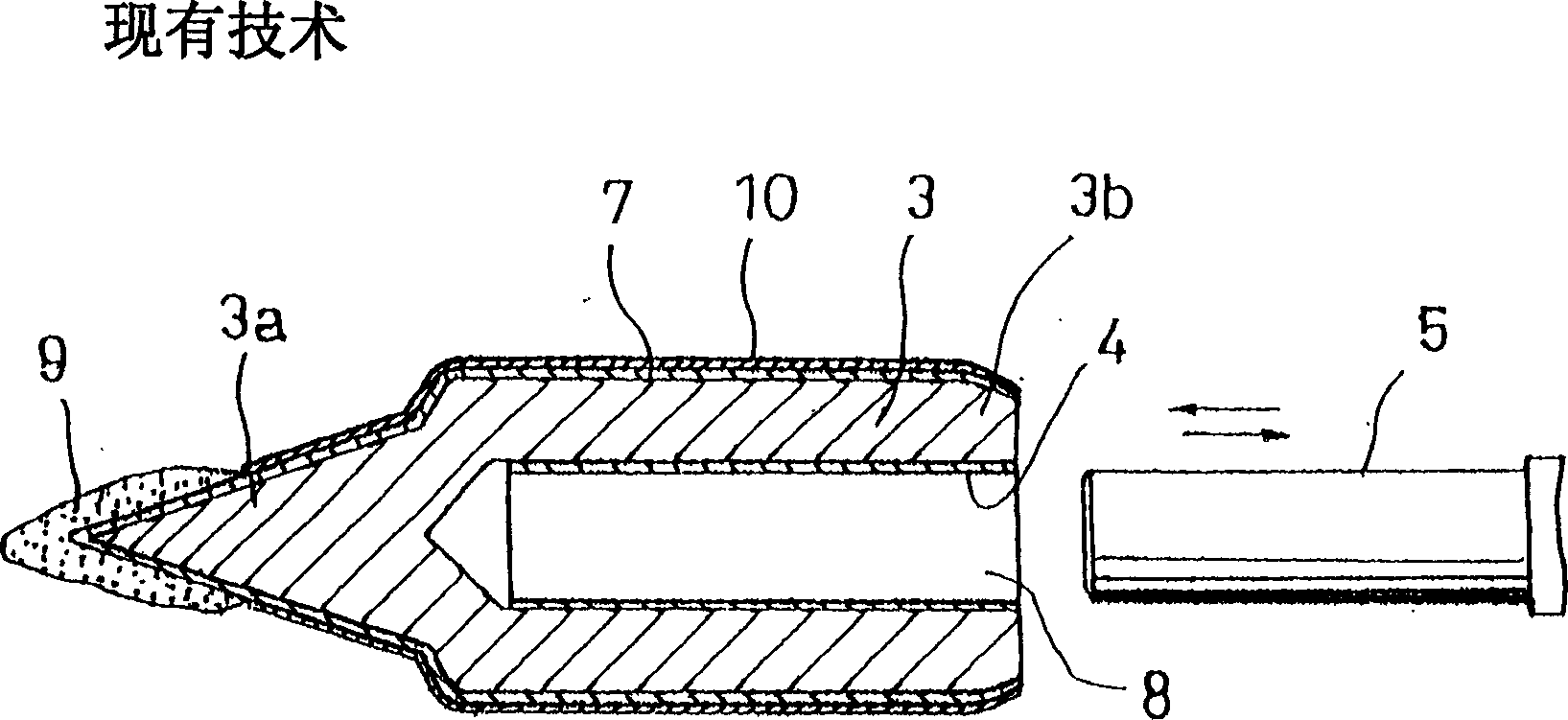
[0047] The scope of application of the surface modification method of the present invention is to replace the chrome plating of the soldering iron tip in the prior art. Or on the inner surface portion of the barrel portion 8 where the copper material of the copper soldering iron tip is exposed. In the prior art, this part is protected with an inner tube 4 . The soldering iron tip 3 used in this embodiment is a pure copper material, and its size and shape are shown in Figure 5 .

[0048] First, the surface modification of the chrome-plated portion that has been used in the past will be described. Image 6 This is an example thereof. In this example, a partial iron plating layer 7 is formed in advance on the front end portion 3 a of the soldering iron tip 3 . The purpose of plating the iron layer 7 on this part is, as mentioned above, to prevent the copper or copper alloy as the raw material of the soldering iron tip 3 from being corroded by the solder, and it is not necessa...

Embodiment 2

[0051] The surface modification of the inner surface of the barrel portion 8 of the copper tip 3 will be described below. The main reason why this part has not been improved so far is that there are technical difficulties in chrome plating to increase oxidation resistance. The following will be described using examples.

[0052] The shape of the sample is the same as in the example, but the diameter of the cylindrical part is 4.2 mm and the depth is 23 mm.

[0053] Figure 7 It means that in this example, the mixture of Al particles and fluoride-based flux was coated on the outer peripheral surface of the soldering iron tip 3 in the same way as in part 10-1 of Example 1, and then evenly coated The inner surface of the barrel portion 8 was then heat-treated under the same conditions as in Example 1 to obtain a surface-modified layer 10-2. After the treatment, in order to observe the state of the inner surface, the sample was cut in half, and the results were observed, and th...

Embodiment 3

[0056] When the copper tip is used without treatment, the corrosion of the solder is very obvious, and the tip portion is quickly consumed. Therefore, it is usually improved by iron plating. In the foregoing embodiment 1, it is the case that iron plating is performed only at the front end portion 3a. However, when this type of plating is performed only on the front end portion, it is necessary to isolate the portion other than the plating tank from the plating tank by shielding, etc., so the manufacturing process is complicated and the cost of the product is increased. favorable.

[0057] In this embodiment, a case where iron plating is performed on the entire surface of a soldering iron tip will be described. First, if Figure 9 As shown, after the iron layer 7 is plated on the entire surface, the copper plated layer 11 is applied on the surface except the front end portion 3a. Then, if Figure 10 As shown, the aforementioned copper plating layer 11 can be surface modifi...


PUM

PropertyMeasurementUnit
Thicknessaaaaaaaaaa
Thicknessaaaaaaaaaa

Abstract

In a tip for an electric soldering iron 3 made of copper or a copper alloy, the outer surface of the tip 3a except the part thereof coated with a solder 9 is coated with a mixture of Al particles and flux, and then the Al particles alone are molten in an inert gas atmosphere, to thereby modify said outer surface so as to have a Cu-Al alloy coating layer of a high Al concentration 10-1. As a result, without using Cr plating, it is possible to provide an electric soldering iron having an excellent resistance to oxidation under high temperature environment and a high heat conductivity.

Description

technical field [0001] The invention relates to an electric soldering iron tip, in particular to a soldering iron tip and a soldering iron for which the surface of a base material is modified into a surface of a Cu-Al alloy with high Al concentration in order to enhance the oxidation resistance in a high temperature environment. Background technique [0002] Soldering is generally used for connection and bonding in the electronics industry. Such a soldering method is roughly divided into a batch soldering method (a collective soldering method) and a manual soldering method. [0003] In the batch soldering method, there are the following methods, that is, the flow soldering method in which components or parts are immersed in molten solder after mounting them on the printed circuit board, and the use of solder particles and flux The reflow soldering method (SMT) method is a soldering method (SMT) method in which the mounted parts are heated and soldered after printing the sol...

Claims


Application Information

Patent Timeline
IPC IPC(8): B23K3/02B23K3/03C23C26/02C23C30/00
CPCB23K3/025C23C30/00C23C26/02B23K3/0369
Inventor 川胜一郎上谷孝司宫崎充彦
Owner HAKKO CO LTD
Why Eureka
Try Eureka