
Inductive coupling type plasma device

A plasma and inductive coupling technology, applied in the direction of plasma, semiconductor/solid-state device manufacturing, chemical/physical/physicochemical process of energy application, etc., can solve problems such as not very effective, incompatible sensors, small ratio, etc.

Inactive Publication Date: 2003-06-25
SAMSUNG ELECTRONICS CO LTD
View PDF3 Cites 12 Cited by
  • Summary
  • Abstract
  • Description
  • Claims
  • Application Information

AI Technical Summary

Problems solved by technology

Positioning the sensors outside the chamber has certain disadvantages:
[0007] 1. It requires some huge, complex dielectric vacuum vessel for a helical inductor, or some large area dielectric orifice in the case of a flat spiral inductor
[0008] 2. An external sensor is not compatible with ultra high voltage (UHV) designs
[0009] 3. The ratio of the conductive portion of the chamber to a wafer susceptor is too small, although it is desirable to have a susceptor surface area much smaller than the ground surface area to achieve control of negative bias on a substrate without applying high RF energy Chance
[0010] 4. It is difficult to scale up the system
However, this treatment is not very effective if one of the precursors, i.e. the stable compound, has a low probability of sticking

Method used


Image

  • Inductive coupling type plasma device
  • Inductive coupling type plasma device
  • Inductive coupling type plasma device

Examples


Embodiment Construction

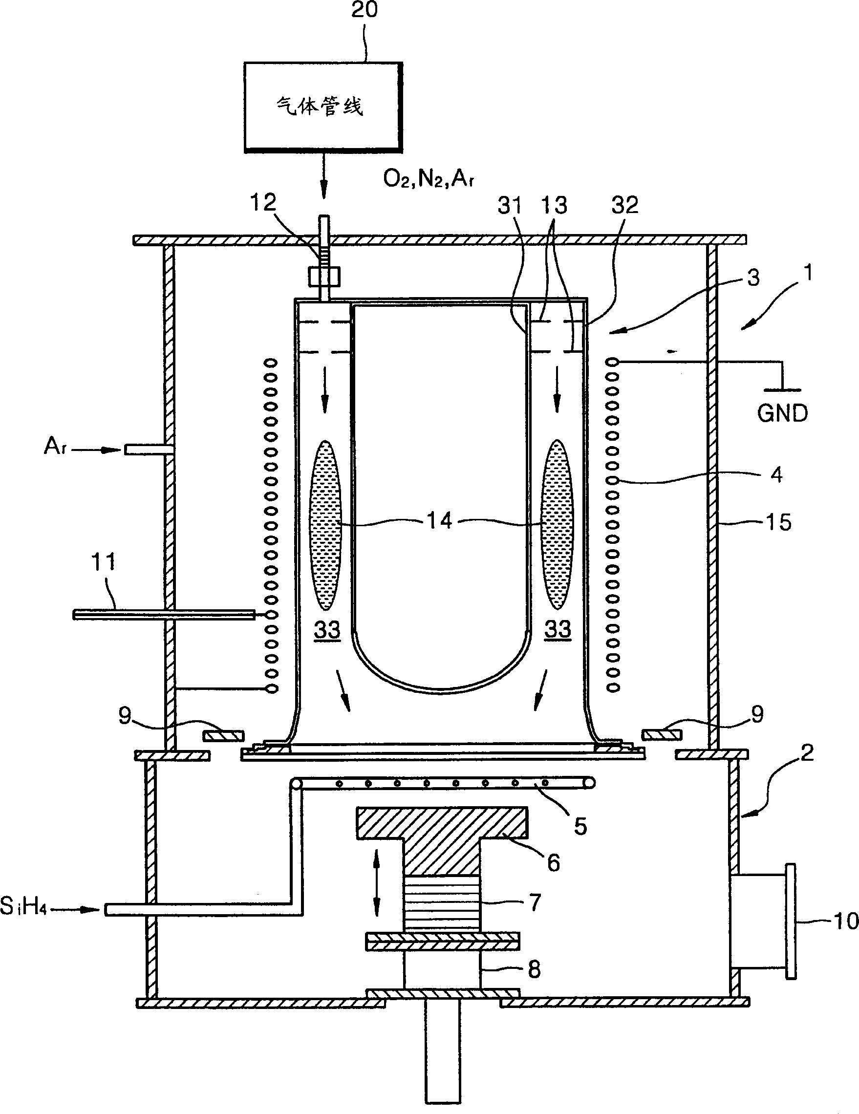
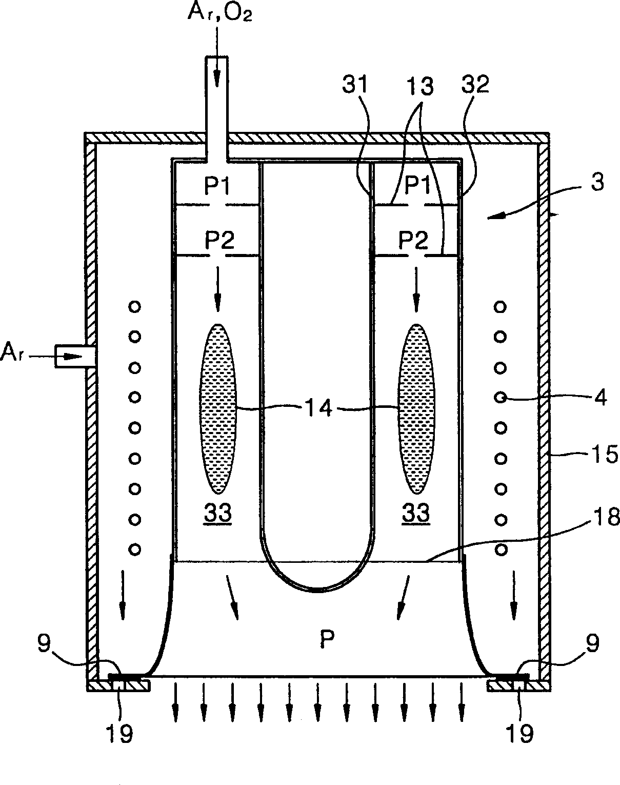
[0026] figure 1 A cross-sectional side view showing a preferred embodiment of an inductively coupled plasma (ICP) apparatus of the present invention. The ICP device includes a top plasma source chamber 1 and a processing chamber 2 .

[0027] A plasma source is arranged inside the top plasma source chamber 1 . The plasma source includes a spiral induction coil 4 and a plasma reactor 3 . The plasma reactor 3 is connected to the supply O by means of a screw cap and a bellows 12 2 , N 2 , Ar and similar gases a gas line 20. The RF energy that excites the plasma in the plasma reactor 3 is fed to one of the turns of the induction coil 4 via an RF cable and an RF feed through (not shown). Both ends of the induction coil 4 are grounded. The entire length of the induction coil 4 is equal to the full wavelength of an RF electromagnetic field. Under these conditions, standing waves of voltage and current are formed in the induction coil 4 . Preferably, the induction coil 4 should...


PUM


Abstract

An inductively coupled plasma apparatus is provided, wherein the inductively coupled plasma apparatus includes a process chamber having a wafer susceptor on which a substrate is installed, a top plasma source chamber which is installed on the process chamber, a reactor, which is installed in the top plasma source chamber, having a channel through which a gas flows, wherein the reactor supplies plasma reaction products to the process chamber, an inductor, having two ends, is installed between the top plasma source chamber and the reactor and is wound around the reactor, an opening which is positioned within a circumferential space in which the inductor is installed between the reactor and the process chamber, and a shutter operable to open and close the opening. Thus, a uniform radial distribution of radicals emanating from a plasma source can be improved.

Description

technical field [0001] The present invention relates to an inductively coupled plasma system used in chemical vapor deposition (CVD). Background technique [0002] The plasma treatment of semiconductor workpieces has the advantage of low treatment temperatures and high efficiency. Such as SiO 2 Deposition can be done using O 2 Plasma source and SiH 4 The gas is carried out at a temperature below 200° C. with a deposition rate of about 100-500 nm / min. However, in order to deposit large areas (up to 300 mm diameter wafers) with high coating uniformity, the plasma source must have a high throughput and form the plasma with a uniform flux. These requirements are met by several high density plasma sources (HDP) available in the art. [0003] Although historically HDPs were developed from electron cyclotron resonance (ECR) plasmas, most recent applications are based on radio frequency (RF) excited inductively coupled plasmas (ICP). The various ICP sources are simple in desig...

Claims


Application Information

Patent Timeline
Patent Type & Authority Applications(China)
IPC IPC(8): H05H1/46B01J19/08C23C16/505H01J37/32H01L21/205H01L21/31
CPCH01J37/32357H01J37/321H01J37/3244
Inventor 尤里·N·托尔马加夫马东俊文昌郁尹惠荣
Owner SAMSUNG ELECTRONICS CO LTD
Learn More