

Technology and equipment for preparing magnetic carbon nanometer tube by plasma
A magnetic carbon nanotube and plasma technology, which is applied in the direction of plasma, inductor/transformer/magnet manufacturing, electrical components, etc., can solve the problems of high arc temperature and hinder the stable progress of the reaction system, so as to achieve cheap equipment and avoid structural defects , Environmentally friendly effect
- Summary
- Abstract
- Description
- Claims
- Application Information
AI Technical Summary
Problems solved by technology
Method used
Image

Examples
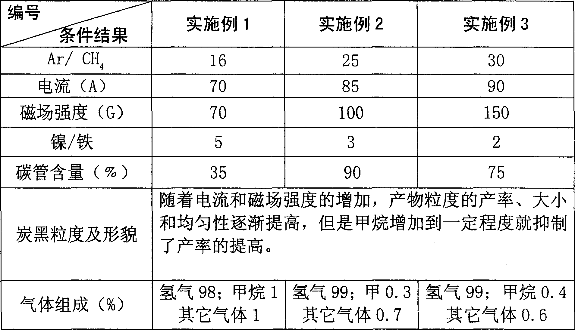
Embodiment 1
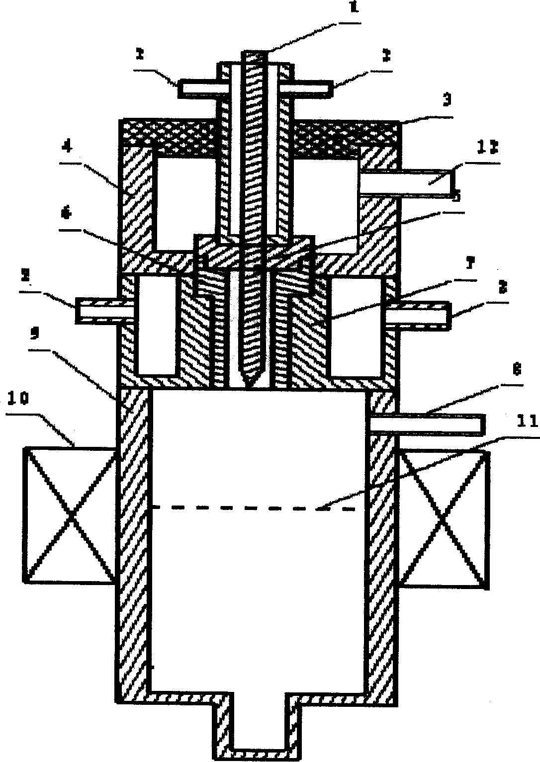
[0017] First, the cooling water is passed into the cooling water pipe 2 at the top of the plasma reactor, flows through the cooling water jacket 7, and finally is discharged from the cooling water pipe 2 at the lower end of the plasma reactor. Argon gas is introduced into the plasma reactor from the inlet pipe 12 . A magnetic coil 10 is attached outside the reactor 9, and its magnetic field strength is kept at 70G. Turn on the power supply and adjust the current to 70A, and the discharge between the cathode 1 and the anode 4 will break down the argon gas flowing into the plasma reactor to generate a plasma jet. The plasma jet junction passes through the ceramic ring 5 and is bounded by the discharge channel 6 and extends into the reactor 9 . Methane is introduced into the reactor 9 from the hydrocarbon raw material inlet pipe 8, and the volume ratio of argon and methane is fed in at a ratio of 16:1. Methane fully contacts with the plasma jet in the reactor 9 under the oxygen...
Embodiment 2
[0019] Using the aforementioned manufacturing device, the cooling water is first passed into the cooling water pipe 2 at the top of the plasma reactor, flows through the cooling water jacket 7, and finally is discharged from the cooling water pipe 2 at the lower end of the plasma reactor. Argon gas is introduced into the plasma reactor from the inlet pipe 12 . A magnetic coil 10 is attached outside the reactor 9, and its magnetic field strength is kept at 100G. Turn on the power supply and adjust the current to 85A, and the discharge between the cathode 1 and the anode 4 will break down the argon gas flowing into the plasma reactor to generate a plasma jet. The plasma jet junction passes through the ceramic ring 5 and is bounded by the discharge channel 6 and extends into the reactor 9 . Methane is introduced into the reactor 9 from the hydrocarbon raw material inlet pipe 8, and the volume ratio of argon and methane is fed in at a ratio of 25:1. Methane fully contacts with t...
Embodiment 3
[0021] Using the aforementioned manufacturing device, the cooling water is first passed into the cooling water pipe 2 at the top of the plasma reactor, flows through the cooling water jacket 7, and finally is discharged from the cooling water pipe 2 at the lower end of the plasma reactor. Argon gas is introduced into the plasma reactor from the inlet pipe 12 . A magnetic coil 10 is attached outside the reactor 9, and its magnetic field strength is kept at 150G. Turn on the power supply and adjust the current to 90A, and the discharge between the cathode 1 and the anode 4 will break down the argon gas flowing into the plasma reactor to generate a plasma jet. The plasma jet junction passes through the ceramic ring 5 and is bounded by the discharge channel 6 and extends into the reactor 9 . Methane is introduced into the reactor 9 from the hydrocarbon raw material inlet pipe 8, and the volume ratio of argon and methane is fed in at a ratio of 30:1. Methane fully contacts with t...
PUM
 Abstract
Description
Claims
Application Information