Producing technology for non-rusting agent pattern and thickening material thereof and semiconductor device producing technology
A resist pattern and process technology, applied in the process field of manufacturing semiconductor devices, can solve problems such as not being developed
- Summary
- Abstract
- Description
- Claims
- Application Information
AI Technical Summary
Problems solved by technology
Method used
Image
Examples
example 1
[0230] -Preparation of resist pattern thickening material-
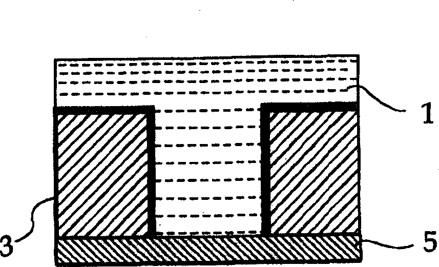
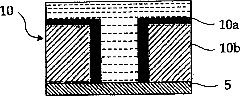
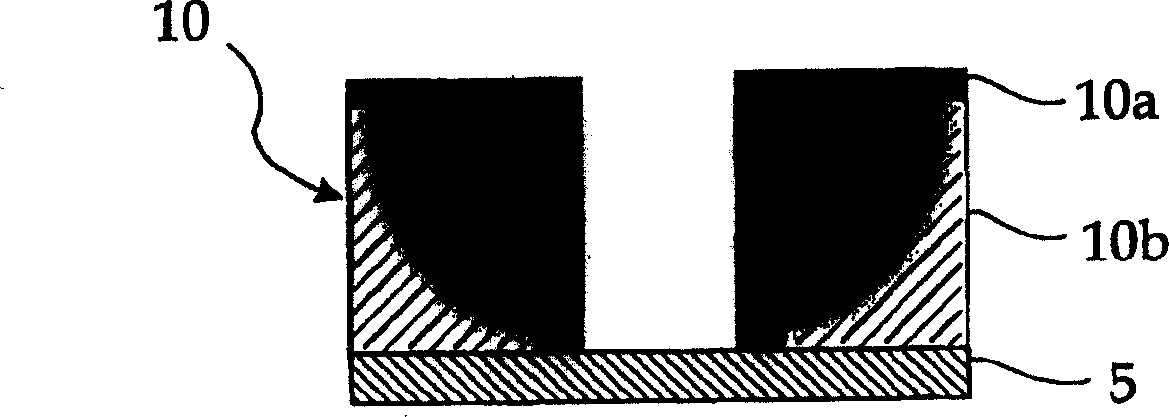
[0231] The resist pattern thickening material A-I of the present invention having the composition shown in Table 1 was prepared. Note that in Table 1, the numerical units in parentheses are parts by mass. In the "Resin" column, "KW-3" is a polyvinyl acetal resin (manufactured by Sekisui Chemical Co., Ltd.). In the column of "phase transfer catalyst", "tetramethylammonium acetate", "tetrabutylammonium acetate" and "tetramethylammonium chloride" were obtained from Sigma-Aldrich Corporation. In the "crosslinking agent" column, "biurea" means tetramethoxymethyl glycoluril. In the "surfactant" column, "PC-6" is a nonionic surfactant (polynuclear phenol surfactant manufactured by Asahi Denka Co., Ltd.) and "TN-80" is a nonionic surfactant (manufactured by Asahi Denka Co., Ltd. Co., Ltd. primary alcohol ethoxylate surfactant). In addition, a mixed solution of pure water (deionized water) and isopropanol (the mass ratio ...
example 2
[0267] As shown in FIG. 9 , an interlayer insulating film 12 is formed on a silicon substrate 11 . As shown in FIG. 10, a titanium film 13 is formed on the interlayer insulating film 12 by a sputtering method. Secondly, if Figure 11 As shown in , a resist pattern 14 is formed. By using the resist pattern 14 as a mask, the titanium film 13 is patterned by reactive ion etching to thereby form the opening 15a. Subsequently, if Figure 12 As shown in , the resist pattern 14 is removed by reactive ion etching, and an opening 15b is formed in the interlayer insulating film 12 by using the titanium film 13 as a mask.
[0268] Secondly, the titanium film 13 is removed by a wet process, such as Figure 13 As shown in , a TiN film 16 is formed on the interlayer insulating film 12 by a sputtering method. Subsequently, Cu film 17 is grown on TiN film 16 by electrolytic plating. Next, as shown in FIG. 14, planarization is performed by CMP so that the barrier metal and the Cu film (f...
example 3
[0273] -Flash memory and its manufacturing process-
[0274] Example 3 is an example of the semiconductor device of the present invention and its manufacturing process using the resist pattern thickening material of the present invention. Note that in Example 3, the resist films 26, 27, 29, and 32 to be described below are resists thickened by the same process as in Examples 1 and 2 using the resist pattern thickening material of the present invention. membrane.
[0275] Figure 18 and 19 It is a top view (plan view) of a FLASH EPROM called a FLOTOX type or ETOX type. Notice Figures 20 to 2 8 is a schematic cross-sectional view for explaining an example of a process for manufacturing a FLASH EPROM. exist Figures 20 to 2 8, the illustration on the left is the memory cell portion (first element region), which is the gate lateral direction of the portion where the MOS transistor with the floating gate electrode is formed ( Figure 18 and 19 Schematic diagram of the cros...
PUM
| Property | Measurement | Unit |
|---|---|---|
| wavelength | aaaaa | aaaaa |
| boiling point | aaaaa | aaaaa |
| coating thickness | aaaaa | aaaaa |
Abstract
Description
Claims
Application Information
 - R&D
- Intellectual Property
- Life Sciences
- Materials
- Tech Scout
- Unparalleled Data Quality
- Higher Quality Content
- 60% Fewer Hallucinations
Browse by: Latest US Patents, China's latest patents, Technical Efficacy Thesaurus, Application Domain, Technology Topic, Popular Technical Reports.
© 2025 PatSnap. All rights reserved.Legal|Privacy policy|Modern Slavery Act Transparency Statement|Sitemap|About US| Contact US: help@patsnap.com


