
Method and apparatus for treating exhaust gas

A waste gas treatment device and waste gas treatment technology, applied in the direction of separation methods, chemical instruments and methods, and methods for chemically changing substances by using atmospheric pressure

Inactive Publication Date: 2007-02-14
NIPPON SANSO CORP +1
View PDF1 Cites 6 Cited by
  • Summary
  • Abstract
  • Description
  • Claims
  • Application Information

AI Technical Summary

Problems solved by technology

In addition, there are problems such as the following: In order to generate plasma under atmospheric pressure, a high-output plasma device is still required

Method used


Image

  • Method and apparatus for treating exhaust gas
  • Method and apparatus for treating exhaust gas
  • Method and apparatus for treating exhaust gas

Examples


example 1

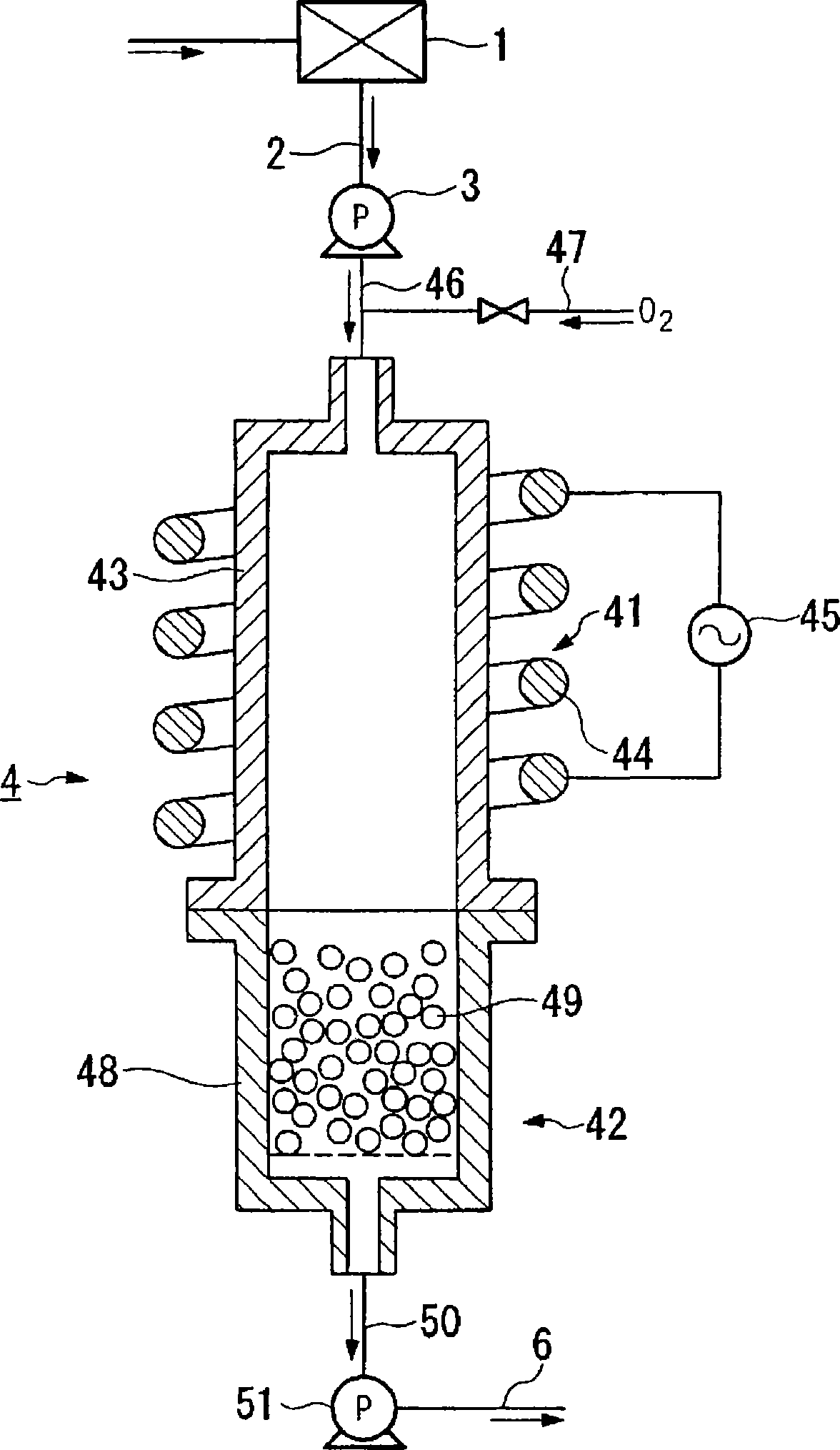
[0091] use figure 1 The shown treatment device treats exhaust gas discharged from a manufacturing facility 1 of semiconductor devices. As the processing tube 43 of the plasma processing unit 41, a cylindrical tube made of alumina with an inner diameter of 40 m is used, and a high-frequency coil 44 is wound thereon, and a frequency of 4 MHz and a maximum output power are applied to the high-frequency coil 44 from an AC power supply 45. The high-frequency current of 1.2 kW generates inductively coupled plasma in the processing tube 43 .

[0092] In addition, as the reactor 48 of the reaction removal part 42, a bottomed cylinder made of quartz with an inner diameter of 40 mm and a length of 150 mm was used, and 300 g of granular calcium oxide with a particle diameter of 1 mm was filled in the inside so that the porosity 50% by volume.

[0093] The pre-pump 3 and the post-pump 51 are operated, and exhaust gas in an excited state from the semiconductor device manufacturing equipm...

example 2

[0100] Using the same processing device as in Example 1, Ar: 20%, Xe: 78%, GeH 4 : 0.1%, B 2 h 6 : 0.1%, SiH 4 : A gas with a composition of 1.8% is introduced into the processing tube 43 under an excited state at a pressure of 50 Torr and a flow rate of 200 SCCM. At the same time, normal-pressure oxygen is introduced from the oxygen supply pipe 47 into the processing pipe 43 at a flow rate of 10 SCCM, and plasma is generated in the processing pipe 43 to oxidize and decompose harmful gas components in the exhaust gas. Thereafter, in the same reaction removal unit 42 as in Example 1, it is brought into contact with calcium oxide and removed.

[0101] For GeH in the exhaust gas discharged from the discharge pipe 50 4 , B 2 h 6 and SiH 4 As a result of quantification of the amount of GeH 4 : 3ppm (lower detection limit) or less, B 2 h 6 : 2ppm (lower detection limit) or less and SiH 4 : 3 ppm (lower detection limit) or less.

example 3

[0103] use figure 1 The treatment device shown is used to treat exhaust gases from a manufacturing facility 1 for semiconductor devices. As the processing tube 43 of the plasma processing part 41, use an inner diameter of 40mm aluminum oxide cylindrical tube, wind a high-frequency coil on it, and apply a frequency of 2MHz to the high-frequency coil from an AC power supply 45, and a maximum output power of The high-frequency current of 1.5 kW generates inductively coupled plasma in the processing tube 43 . In addition, as the reactor 48 of the reaction removal part 42, use an inner diameter of 40 mm and a length of 150 mm stainless steel with a bottom cylinder, and fill 20 kg of granular calcium oxide with a particle diameter of 3 mm in the interior so that the porosity is 50 mm. volume%.

[0104] The pre-pump 3 and the post-pump 51 are operated to introduce exhaust gas in an excited state from the semiconductor device manufacturing facility 1 through the introduction pipe 46...


PUM


Abstract

A method for treating an exhaust gas, which comprises the steps of introducing an exhaust gas being in an exited state in a facility for manufacture of a semiconductor device into a plasma treatment portion of a treating section under a reduced pressure, introducing the exhaust gas being maintained in an exited state by a plasma generating in the plasma treatment portion into a reactor in a removal reaction section, reacting the exhaust gas with a removing reaction agent comprised of particulate calcium oxide packed in the reactor and removing harmful gas components in the exhaust gas. The method may further include the step of supplying oxygen into the plasma treatment portion so as to subject the harmful gas components to oxidation decomposition in the presence of a plasma and then reacting the decomposed gas components with the removing reaction agent.

Description

technical field [0001] The present invention relates to an exhaust gas treatment method and an exhaust gas treatment device for removing harmful gas components in exhaust gas exhausted from manufacturing equipment used in the manufacture of semiconductor devices, flat panel displays, solar cells, or magnetic thin plates. [0002] This application claims priority to Japanese Patent Application No. 2004-020975 for which it applied on January 29, 2004, and uses the content here. Background technique [0003] In the exhaust gas discharged from the above-mentioned manufacturing equipment, Ar and CF are also contained. 4 、C 2 f 6 、SiF 4 and other reaction products. The reaction products contained in such waste gas have a high global warming coefficient and cannot be discharged directly but need to be discharged after harmless treatment. In addition, since the waste gas becomes atmospheric pressure in the previous stage of detoxification treatment, a polymer reaction product, ...

Claims


Application Information

Patent Timeline
Patent Type & Authority Applications(China)
IPC IPC(8): B01D53/68B01J3/00B01J19/08B01J19/12
CPCB01J19/088B01J2219/0894B01J2219/0892B01J2219/0883B01D53/68B01D53/34
Inventor 大见忠弘长谷川英晴石原良夫铃木克昌
Owner NIPPON SANSO CORP
Learn More